Electrical terminal and electrical connector thereof

a technology of electrical terminals and connectors, which is applied in the direction of coupling contact members, fixed connections, coupling device connections, etc., can solve the problems of pins not matching with the soldering holes of the circuit board, assembly difficulties, and the lack of a structure for positioning the u-shaped body of the electrical insulation base, so as to avoid the deformation of the electrical terminal

Active Publication Date: 2020-08-27
DONGGUAN LUXSHARE TECH CO LTD
View PDF0 Cites 3 Cited by
  • Summary
  • Abstract
  • Description
  • Claims
  • Application Information

AI Technical Summary

Benefits of technology

[0005]In order to solve the problem of fixing and positioning the electrical terminal in the electrical connector, one or some embodiments of this disclosure propose an electrical terminal and an electrical connector. Accordingly, the electrical terminal can be fixed and positioned effectively, thereby making the electrical connector easy in assembling and easy in mounting to the circuit board.
[0020]In one or more embodiments of this disclosure, the electrical terminal includes at least one interference lug to match the at least one installation trough of the base, for positioning and guiding the electrical terminal, thereby ensuring that the electrical terminal can be inserted into the at least one installation trough in the correct direction while maintaining the relative position of the electrical terminal in the base. Furthermore, other structures disclosed in one or more embodiments of this disclosure further provide positioning and guiding functions for the electrical terminal, thereby ensuring that the electrical terminal from being installed incorrectly, and avoiding the deformation of the electrical terminal.

Problems solved by technology

Consequently, the pins cannot match with the soldering holes of the circuit board.
Under such condition, all of the pins cannot be aligned with the soldering holes, resulting in assembly difficulties.
Moreover, the electrical-insulated base also lacks a structure for positioning the U-shaped body.
Thus, during the assembly process, the U-shaped body may be detached from its proper position in the electrical-insulated base, thereby further worsening the problem of the poor alignments between the pins and the soldering holes.
Especially, when the electrical connector includes plural power terminals, the pin alignment problem may be more serious.

Method used


Image

  • Electrical terminal and electrical connector thereof
  • Electrical terminal and electrical connector thereof
  • Electrical terminal and electrical connector thereof

Examples


first embodiment

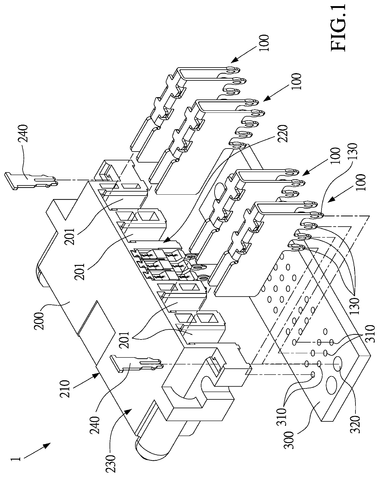
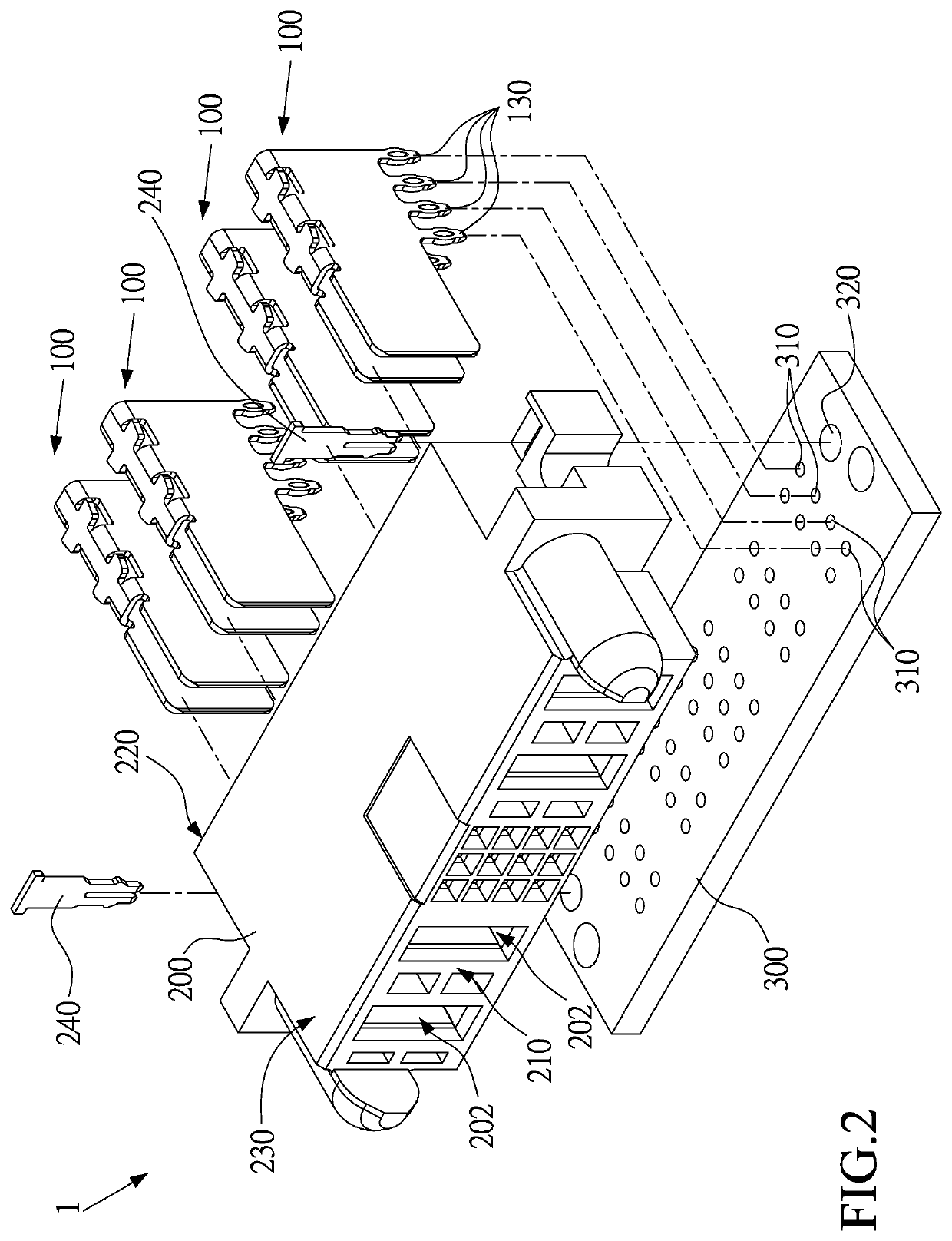
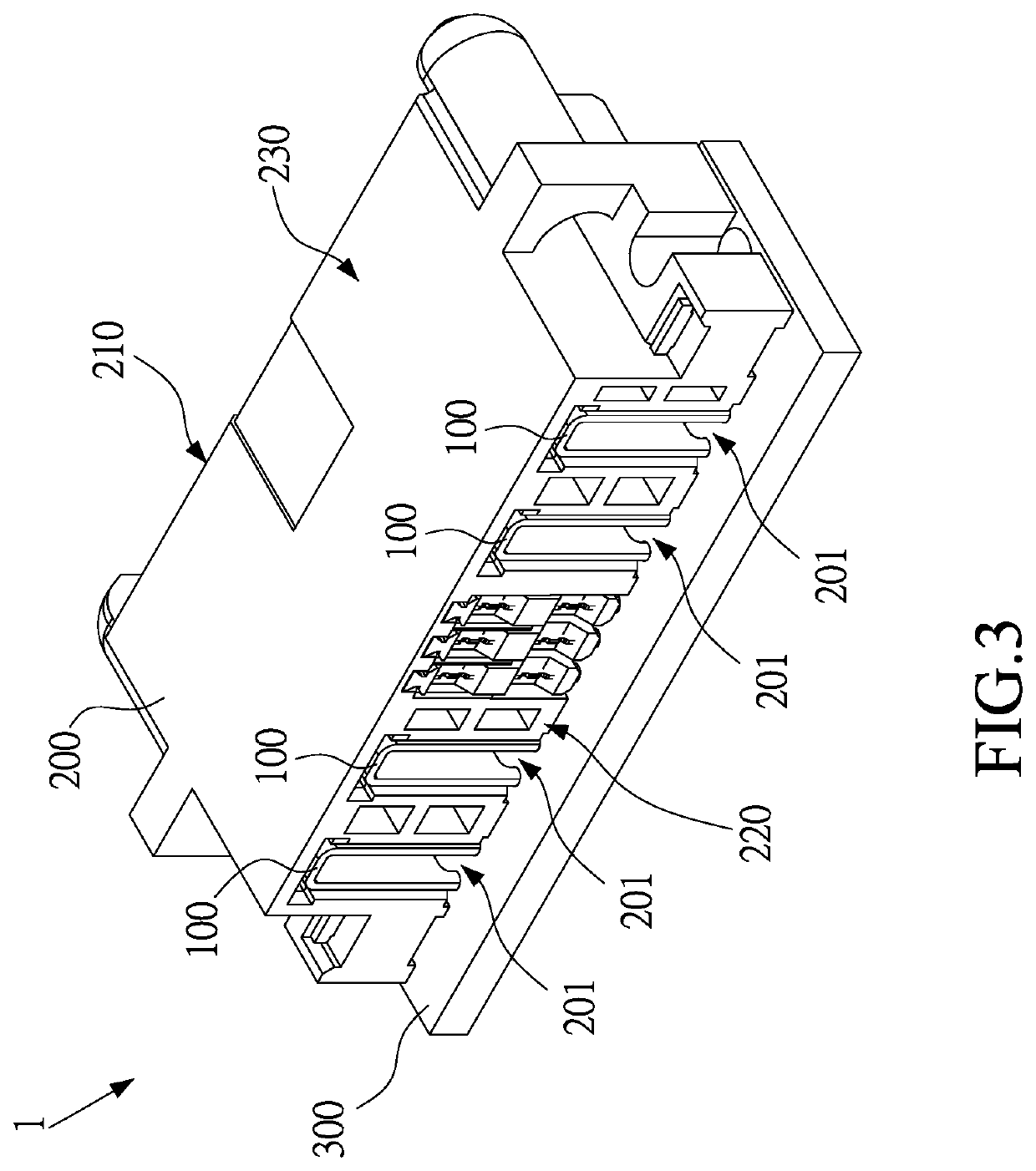
[0037]Please refer to FIGS. 1, 2, 3, and 4, where an electrical terminal 100 according to this disclosure is illustrated. In this embodiment, the electrical terminal 100 is adapted to be combined with a base 200 to form an electrical connector 1. The electrical connector 1 may be further soldered or fixed to a circuit board 300 by other ways. The electrical terminal 100 may be, but not limited to, a power terminal for power transmission or a signal terminal for signal transmission.

[0038]As shown in FIG. 4, the electrical terminal 100 comprises a terminal body 110, at least one interference lug 120, and at least one circuit connection part 130. The terminal body 110 includes a front end 111 and a back end 112 in a longitudinal direction Y. The interference lug 120 protrudes from a surface of the terminal body 110, the interference lug 120 is arranged in parallel to the longitudinal direction Y, and the interference lug 120 extends outwardly in a horizontal direction X perpendicular t...

second embodiment

[0050]Please refer to FIGS. 8, 9, and 10, where an electrical connector according to this disclosure is illustrated. In this embodiment, the electrical connector 1 comprises an electrical terminal 100 and a base 200.

[0051]As shown in FIG. 11, most of the features of the electrical terminal 100 of the second embodiment are the same as that of the first embodiment, and the differences between the embodiments will be described below. In the second embodiment, the electrical terminal 100 further comprises a contact part 140 on the front end 111 of the terminal body 110. The contact part 140 comprises a plurality of elastic contact pieces 142 extending outwardly in the longitudinal direction Y from each of the lateral plates 140. The elastic contact pieces 142 are configured in pairs, and a front end of each of the elastic contact pieces 142 forms a guiding bevel 144 inclined inwardly.

[0052]As shown in FIGS. 12, 13, and 14, the contact part 140 is inserted into the insertion hole 202 in ...


PUM


Abstract

An electrical terminal includes a terminal body, at least one interference lug, and at least one circuit connection part. The terminal body includes a front end and a back end in a longitudinal direction. The interference lug is arranged in parallel to the longitudinal direction and extends outwardly in a horizontal direction perpendicular to the longitudinal direction. The at least one circuit connection part is connected to the terminal body. An electrical connector is also provided, and the electrical connector includes a base and the electrical terminal. The base includes at least one installation trough, and a guiding groove is arranged in the at least one installation trough, the at least one interference lug is adapted to slide into the guiding groove, so as to guide and position the electrical terminal.

Description

CROSS-REFERENCE TO RELATED APPLICATION[0001]This non-provisional application claims priority under 35 U.S.C. § 119(a) to Patent Application No. 108139363 in Taiwan, R.O.C. on Oct. 30, 2019, the entire contents of which are hereby incorporated by reference.BACKGROUNDTechnical Field[0002]This disclosure relates to an electrical terminal and an electrical connector, in particular, to an electrical terminal and an electrical connector including the electrical terminal.Related Art[0003]A large electrical terminal, especially a power terminal, is usually made of a metal sheet bent into a U-shaped structure. A pin of the electrical terminal extends from the bottom (the opening side of the U-shaped structure). An electrical-insulated base for installing a power supply terminal is provided with an installation trough is opened at the bottom of the electrical-insulated base. The U-shaped body of the electrical terminal is installed in the installation trough, and the pin protrudes from the bo...

Claims


Application Information

Patent Timeline
Patent Type & Authority Applications(United States)
IPC IPC(8): H01R12/70H01R12/55H01R13/502H05K3/30H05K3/34
CPCH05K2201/10431H01R12/7011H05K3/301H05K2201/10189H05K3/3447H01R13/502H01R12/55H05K2201/10742H01R13/02H01R13/40H01R12/58H01R13/41H01R13/113H01R12/7088H01R12/707H05K2201/1078H05K2201/10295H05K2201/10856
Inventor HUNG, YUNG-CHIH
Owner DONGGUAN LUXSHARE TECH CO LTD
Why Eureka
Try Eureka