
Target Instrument And Surveying System

Active Publication Date: 2020-08-27
KK TOPCON
View PDF5 Cites 1 Cited by
  • Summary
  • Abstract
  • Description
  • Claims
  • Application Information

AI Technical Summary

Benefits of technology

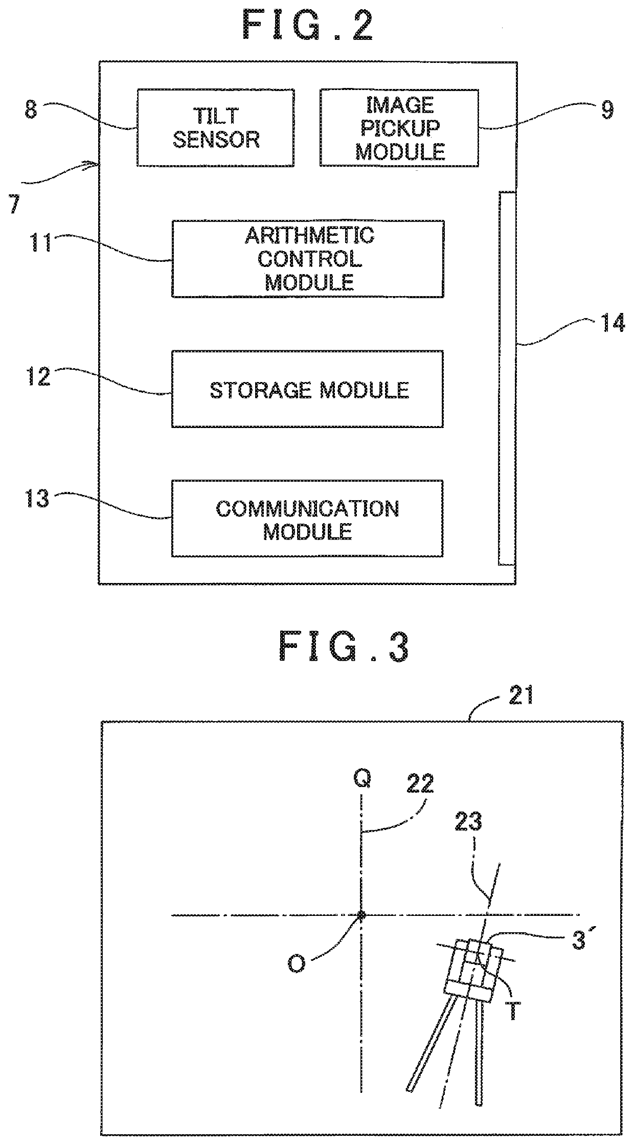
The present invention is a target instrument and surveying system that can accurately measure a measuring point even if the target instrument is not perfectly vertically supported or requires no skill or concentration for support. The target instrument includes a pole, prism, and terminal device with an image pickup module and tilt sensor. The system calculates the tilt direction of the target instrument based on the tilt angles in two axial directions, and corrects the tilt angles to improve the measurement accuracy. This frees a measurement operator from the task of vertically erecting the target instrument and improves workability and accuracy.

Problems solved by technology

In this case, whether the target instrument is supported in a vertical state or stably supported, is dependent upon the worker's skill level or concentration, further there is also a problem which an error becomes considerable in a case where a distance from the lower end of the support pole to the prism increases.

Method used


Image

  • Target Instrument And Surveying System
  • Target Instrument And Surveying System
  • Target Instrument And Surveying System

Examples


Embodiment Construction

[0017]By referring to the drawings, a description will be given below on an embodiment of the present invention.

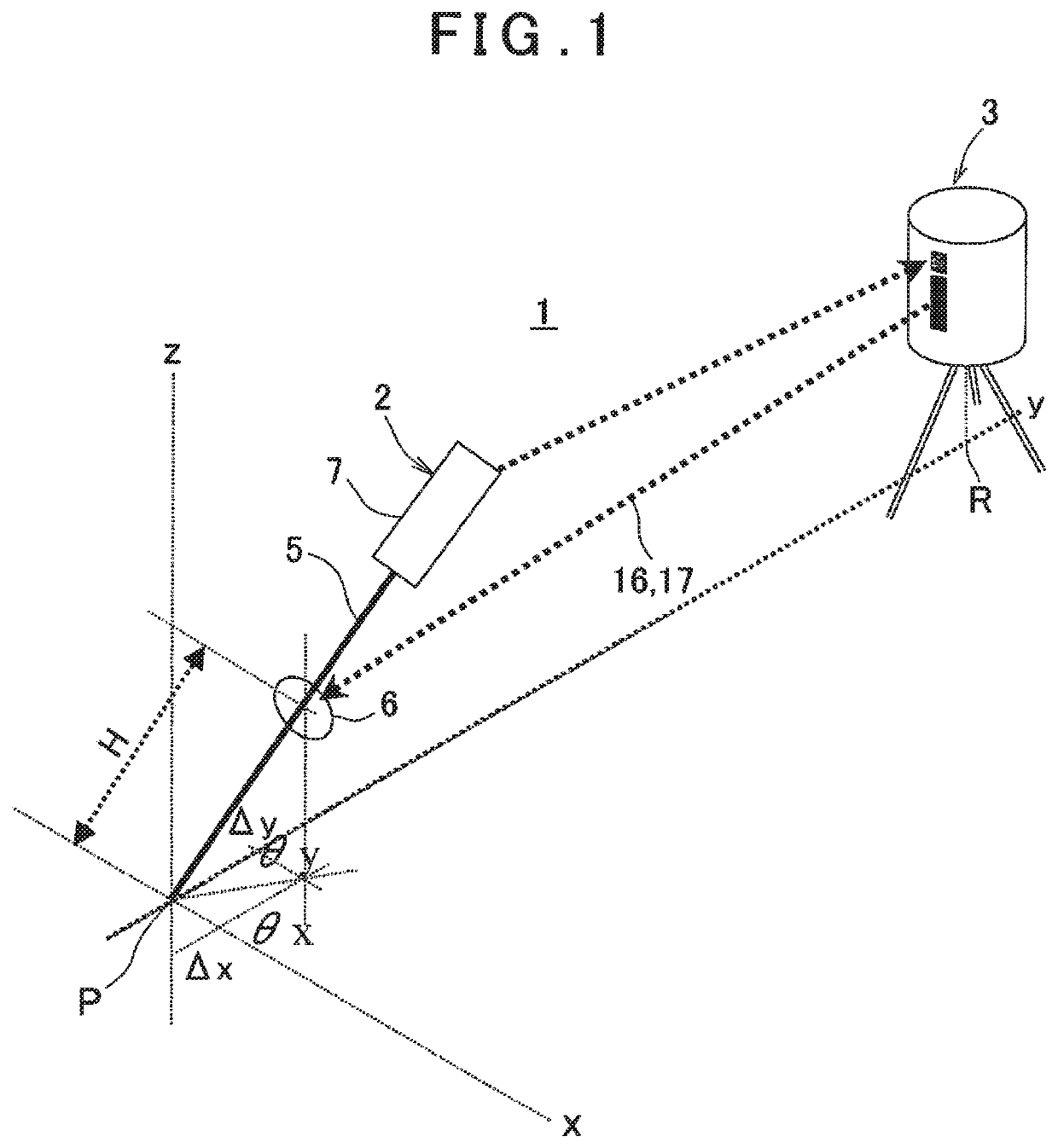
[0018]FIG. 1 shows a surveying system 1 according to an embodiment of the present invention and, in FIG. 1, a reference numeral 2 denotes a target instrument and a reference numeral 3 denotes a surveying instrument having a tracking function, e.g., a total station.

[0019]The total station 3 performs the three-dimensional measurement, and stores a measurement result in a built-in storage module. Further, the total station 3 may include a communication device and transmit a measurement result to the target instrument 2.

[0020]First, a description will be given on the target instrument 2.

[0021]A lower end part of a pole 5 is a ferrule, and a lower end of the ferrule is installed on a measuring point P. A prism (e.g., a corner cube or an all-around prism) 6 is provided at a predetermined distance (a known distance H) from the lower end of the ferrule, and a distance between an o...


PUM


Abstract

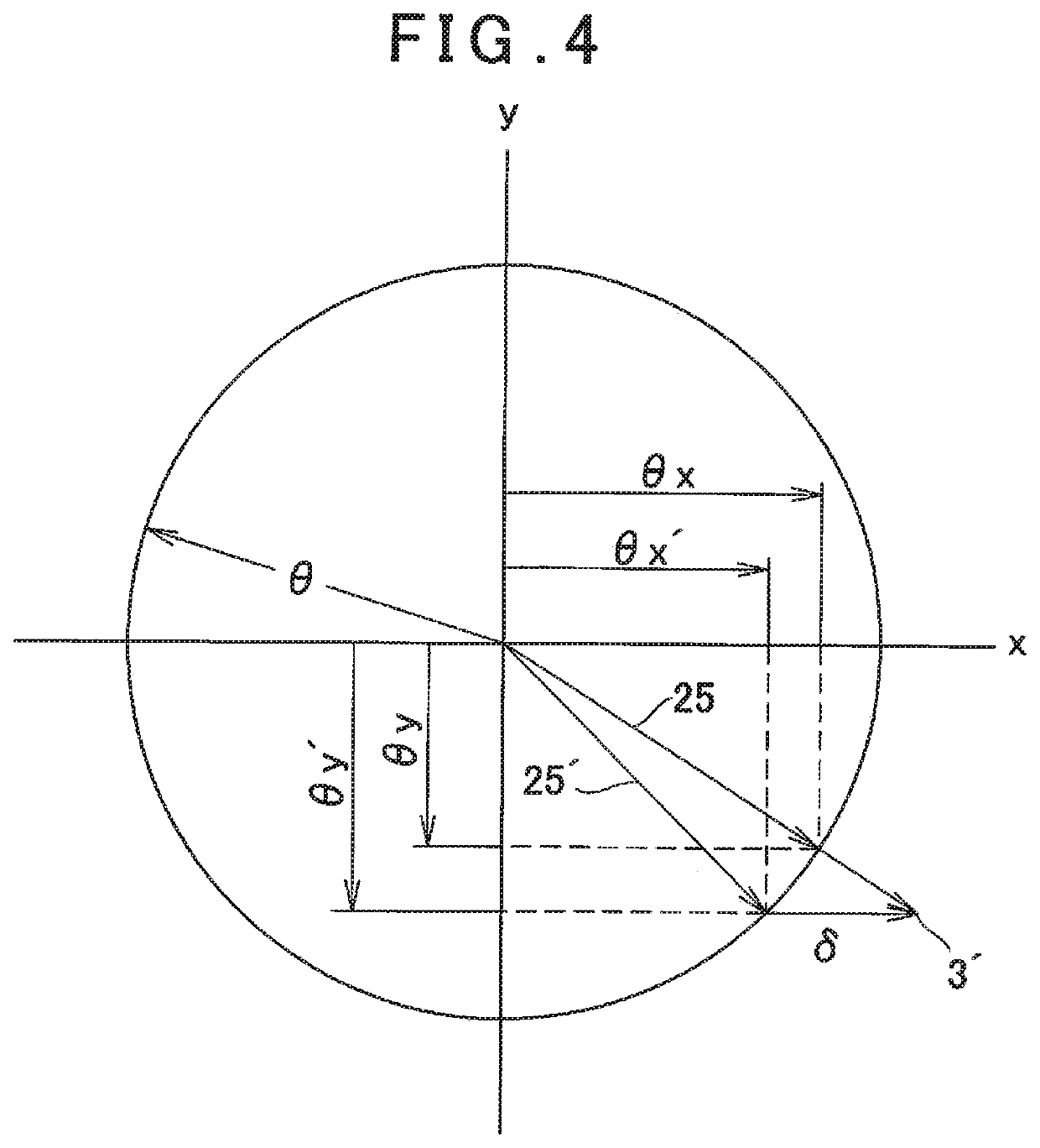
Provided is a target instrument including a pole, a prism provided on the pole, and a terminal device provided on the pole, wherein the terminal device comprises an image pickup module, a tilt sensor which detects tilts in two axial directions, and an arithmetic control module, wherein the image pickup module acquires an image which includes a reference object, the tilt sensor detects a tilt angle of a target instrument, and the arithmetic control module calculates a tilt direction of the target instrument from a position of the reference object in the image, calculates a tilt direction of the target instrument based on tilt angles in the two axial directions of the tilt sensor, acquires a deviation between the two tilt directions, and corrects the tilt angles in the two axial directions of the tilt sensor to tilt angles in directions parallel to an optical axis of the image pickup module and orthogonal to the optical axis based on the deviation.

Description

BACKGROUND OF THE INVENTION[0001]The present invention relates to a target instrument which is erected on a measuring point and has a prism as an object to be measured, and to a surveying system which measures the measuring point via the measurement of the prism.[0002]In case of measuring a measuring point, a target instrument having a prism provided on a support pole is used. When the target instrument is erected on the measuring point and the prism is measured by a surveying instrument, the measuring point is measured. Further, in case of using the surveying instrument with a tracking function, the target instrument is sequentially moved to the different measuring points, the prism is tracked by the surveying instrument, and the measuring points are sequentially measured.[0003]In this case, in order to accurately measure a measuring point, the prism must be placed vertically above the measuring point. Usually, the prism is provided on an upper part of the support pole, and a worke...

Claims


Application Information

Patent Timeline
IPC IPC(8): G01S7/48G01S17/08
CPCG01S7/4808G01S17/08G01S7/4804G01C15/06G01C1/04
Inventor KUMAGAI, KAORUCHIBA, MINORUSUGIURA, AKINOBU
Owner KK TOPCON
Learn More