Re-Quantization Device Having Noise Shaping Function, Signal Compression Device Having Noise Shaping Function, and Signal Transmission Device Having Noise Shaping Function
a signal compression and quantization device technology, applied in the direction of analogue conversion, code conversion, electrical equipment, etc., can solve the problems of reducing sound quality, increasing the total amount of quantization noise, and increasing the quantization noise, so as to suppress the deterioration of the signal-to-noise ratio and suppress the increase of quantization noise
- Summary
- Abstract
- Description
- Claims
- Application Information
AI Technical Summary
Benefits of technology
Problems solved by technology
Method used
Image
Examples
first embodiment
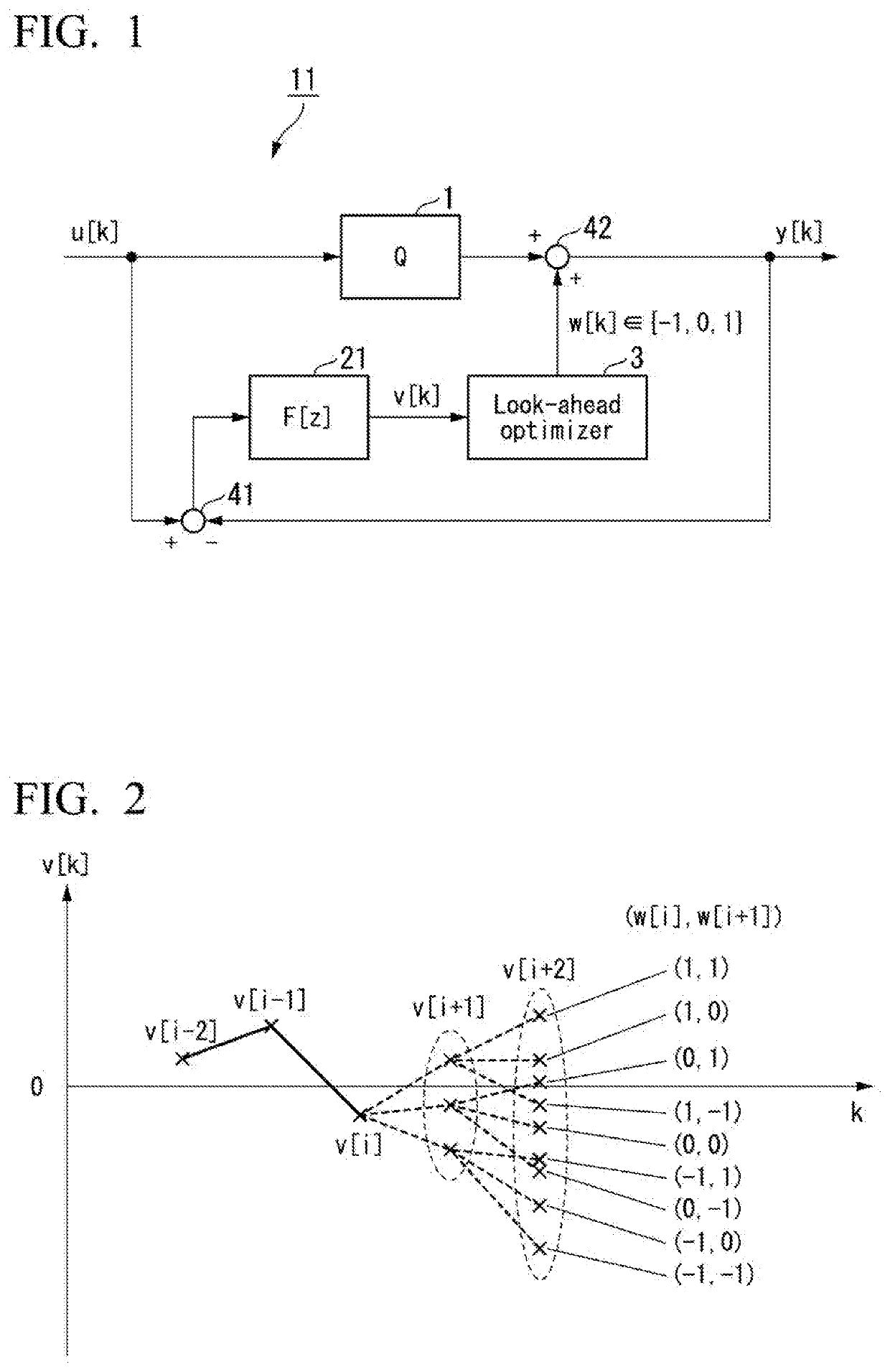
[0031]A configuration of a re-quantization device 11 according to a first embodiment of the present invention is shown in FIG. 1. The re-quantization device has a noise shaping function to convert a high resolution PCM signal u[k] into a low resolution PCM signal y[k].
[0032]The low resolution PCM signal y[k] is a discrete time signal having a value of an integer. For convenience of description, it is assumed that the value of the high resolution PCM signal u[k] is given in a fixed-point format and has an integer part and a fractional part. In the re-quantization device 11, a resolution is reduced by an amount of the fractional part of the high resolution PCM signal u[k], and thus the low resolution PCM signal y[k] is output. The re-quantization device 11 having a noise shaping function is executed through batch processing instead of real-time processing, and thus causality is not necessarily required in internal processing.
[0033]An operation will be described as follows. The high re...
second embodiment
[0052]A second embodiment of the present invention relates to a re-quantization device having a noise shaping function in a case where a low resolution signal y[k] which is an output signal of the re-quantization device includes bits which are not directly related to a high resolution signal u[k] which is an input signal of the re-quantization device. FIG. 10 shows an example of a bit configuration of a low resolution signal y[k]. The low resolution signal y[k] is a binary 16-bit signal based on a complement of 2. However, a known noise signal s[k] being data of low-order 3 bits is data not directly related to a high resolution signal u[k], and a part r[k] of high-order 13 bits is directly related to the high resolution signal u[k]. A technique for making the influence of a known noise signal s[k] appear as only re-quantization noise even when 16-bit data of y[k] is reproduced as it is by performing noise shaping in consideration of the value of the known noise signal s[k] in genera...
third embodiment
[0058]In a third embodiment of the present invention, the re-quantization device 11 having a noise shaping function executed through batch processing in the first embodiment is executed by real-time processing.
[0059]In the re-quantization device having a noise shaping function in the first embodiment, when a present time is set to be k=i, values of filter output signals v[i+1] to v[i+N] are used in obtaining the value w[i] of an additional signal at the present time, which means that values of high resolution signals u[i] to u[i+N] which are input signals of the re-quantization device are required. Here, when a low resolution signal y[k] which is an output signal of the re-quantization device is delayed by N steps or more, it is apparent that the same signal processing as that in the first embodiment can be executed in real time.
[0060]In the third embodiment of the present invention, the processing in the first embodiment is executed in real time, but the processing in the second em...
PUM
 Abstract
Description
Claims
Application Information
 - R&D
- Intellectual Property
- Life Sciences
- Materials
- Tech Scout
- Unparalleled Data Quality
- Higher Quality Content
- 60% Fewer Hallucinations
Browse by: Latest US Patents, China's latest patents, Technical Efficacy Thesaurus, Application Domain, Technology Topic, Popular Technical Reports.
© 2025 PatSnap. All rights reserved.Legal|Privacy policy|Modern Slavery Act Transparency Statement|Sitemap|About US| Contact US: help@patsnap.com


