Switch module
a switch module and module technology, applied in the field of switch modules, can solve the problems of increasing the insertion loss of this series-connected switch, difficult to find suitable values, and difficult to reduce the insertion loss of the switch module including the shunt-connected switch, so as to reduce the insertion loss of the switch module
- Summary
- Abstract
- Description
- Claims
- Application Information
AI Technical Summary
Benefits of technology
Problems solved by technology
Method used
Image

Examples
first embodiment
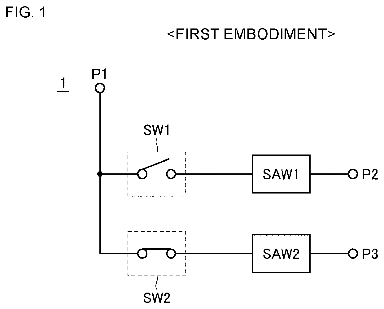
[0041]FIG. 1 is a circuit diagram of a switch module 1 according to a first embodiment. As shown in FIG. 1, the switch module 1 includes a common terminal P1, input / output terminals P2 and P3, first and second filters SAW1 and SAW2, which are surface acoustic wave (SAW) filters, and first and second switches SW1 and SW2. The pass band of the second filter SAW2 is included in the stop band of the first filter SAW1. The switch module 1 is a single-pole double-throw (SPDT) switch module. Alternatively, the switch module 1 may be a SPnT (n is three or greater) switch module.
[0042]The common terminal P1 corresponds to a first terminal of an embodiment of the disclosure. The pass band of the first filter SAW1 corresponds to a first frequency band of an embodiment of the disclosure, and the stop band of the first filter SAW1 corresponds to a second frequency band of an embodiment of the disclosure. The pass band of the second filter SAW2 corresponds to a third frequency band of an embodime...
second embodiment
[0092]In the first embodiment, without the provision of a shunt-connected switch, a connection path from a series-connected switch to a SAW filter is not connected to a ground point so that the impedance from the common terminal P1 to each input / output terminal can be made to be in the open state. However, other measures may be taken to make the impedance from the common terminal P1 to each input / output terminal be in the open state. Any measures may be taken not to connect a connection path from a series-connected switch to a SAW filter to a ground point. In a second embodiment, shunt-connected switches are provided, and regardless of whether series-connected switches are ON or OFF, the shunt-connected switches are turned OFF, so that a connection path from a series-connected switch to a SAW filter is not connected to a ground point. In the second embodiment, the configurations of elements designated by like reference numerals of the first embodiment are similar to those of the fir...
third embodiment
[0102]In the first and second embodiments, SPDT and SP3T switch modules are used as examples of a SPnT switch module according to an embodiment of the disclosure. However, the disclosure may be applicable to other types of SPnT switch modules. In a third embodiment, a SP6T switch module is used as an example of the SPnT switch module.
[0103]FIG. 13 is a circuit diagram of a switch module 3 according to the third embodiment. As shown in FIG. 13, the switch module 3 includes a common terminal P1, first, second, and third switches SW1, SW2, and SW3, input / output terminals P12, P13, P22, P23, P32, and P33, and duplexers DUP1, DUP2, and DUP3.
[0104]The first switch SW1 switches between electrical connection and disconnection between the duplexer DUP1 and the common terminal P1. The second switch SW2 switches between electrical connection and disconnection between the duplexer DUP2 and the common terminal P1. The third switch SW3 switches between electrical connection and disconnection betw...
PUM
 Abstract
Description
Claims
Application Information
 - R&D
- Intellectual Property
- Life Sciences
- Materials
- Tech Scout
- Unparalleled Data Quality
- Higher Quality Content
- 60% Fewer Hallucinations
Browse by: Latest US Patents, China's latest patents, Technical Efficacy Thesaurus, Application Domain, Technology Topic, Popular Technical Reports.
© 2025 PatSnap. All rights reserved.Legal|Privacy policy|Modern Slavery Act Transparency Statement|Sitemap|About US| Contact US: help@patsnap.com