Optical fiber connection system

a fiber optic connection and optical fiber technology, applied in the field of optical fiber connection systems, can solve the problems of limiting the interconnection density, and reducing the interconnection density of multi-fiber ferruled connectors such as mpo/mto connectors, and reducing the interconnection density

Active Publication Date: 2020-07-30
3M INNOVATIVE PROPERTIES CO
View PDF0 Cites 33 Cited by
  • Summary
  • Abstract
  • Description
  • Claims
  • Application Information

AI Technical Summary

Problems solved by technology

Polarity is managed by use of transmit and receive pairs (duplex cabling), but becomes more complex with multi-fiber connectivity which support multiple duplex pairs such as MPO / MTP connectors.
Conventional single fiber ferrule type connectors offer easy reconfiguration, but have the drawback of high optical loss (0.2-0.3 dB) and even higher loss for multi-fiber ferruled connectors such as MPO / MTO connectors (0.35-0.7 dB).
In addition, space required for ferruled connectors limits the interconnection density.
However, handling 250-micron fiber during preparation, fuse, storage can be troublesome.
However, these mechanical splices employ index matching gels which are not solid materials and therefore, provide no structural integrity.

Method used


Image

  • Optical fiber connection system
  • Optical fiber connection system
  • Optical fiber connection system

Examples


first embodiment

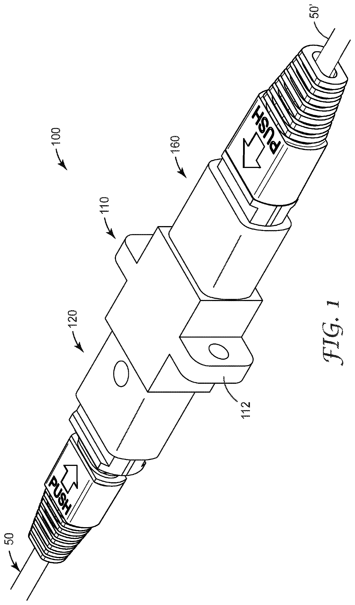
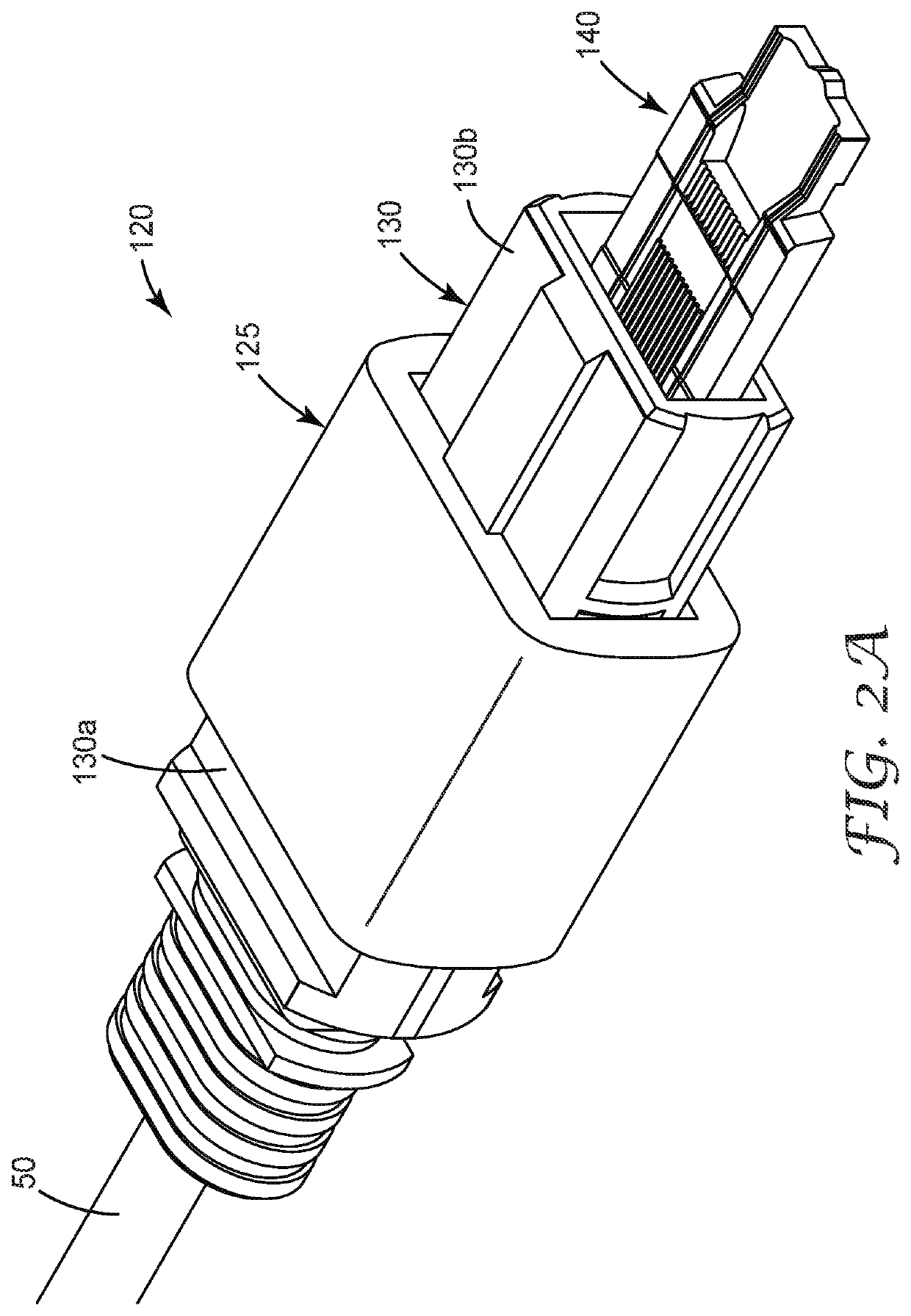
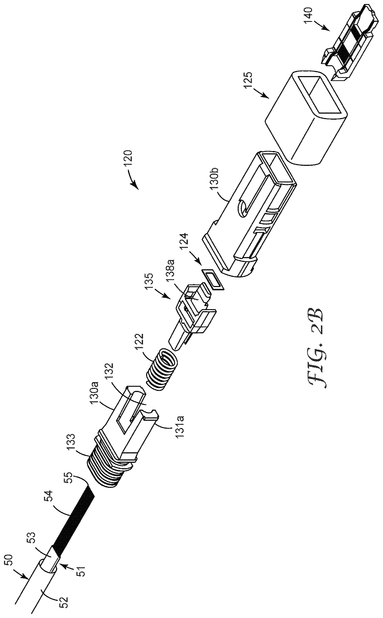
[0043]In a first embodiment, the optical fiber connection system comprises an alignment mechanism and an optical coupling material. The alignment mechanism can be formed using a sol casting resin to generate net shape silica ceramic parts such as is described in U.S. patent application Ser. No. 15 / 695,842, herein incorporated by reference in its entirety.

[0044]In one aspect, the optical coupling material can be an optical adhesive that can be used to permanently secure the plurality of parallel optical fibers in the exemplary splice element. An exemplary optical adhesive can be cured with actinic radiation via a rapid and straightforward procedure using an eye-safe visible, e.g., blue, LED light source such as is described in U.S. patent application Ser. No. 15 / 695,842, herein incorporated by reference in its entirety. In an alternative aspect, the optical coupling material can be an index matching gel configured to optimize he signal transmission thought the optical fiber splice, t...

third embodiment

[0134]an exemplary optical fiber connection system is shown in FIGS. 22A-22B through 26A-26C. Optical fiber splice connection system 600 provides a ferrule-less interconnection system to optically couple a plurality of first and second optical fibers. Optical fiber splice connection system 600 comprises a pair of bare fiber holders, such as first and second bare fiber holders 620, 620′. In one aspect, the bare fiber holders may be secured together with an auxiliary clamping member (not shown) or by an adhesive. The first and second bare fiber holders 620, 620′ can each be field terminated, installed or mounted onto an optical fiber cable or fiber ribbon in the field followed by assembly of the first and second bare fiber holders to form either a semi-permanent or permanent optical connection. Alternatively, the first and second bare fiber holders can be factory terminated, installed or mounted onto an optical fiber cable or fiber ribbon in the factory followed by assembly of the fir...


PUM

PropertyMeasurementUnit
insertion lossaaaaaaaaaa
angleaaaaaaaaaa
angleaaaaaaaaaa

Abstract

An optical fiber connection system (600) configured to interconnect a plurality of first and second optical fibers (54, 54′) is described. The connection system comprises a first bare fiber holder (620) that includes a clamping plate (540) having an interconnection portion (544) with a generally planar surface, wherein bare ends of the plurality of first optical fibers (54) are disposed adjacent to interconnection portion (544) and wherein the plurality of first optical fibers (54) are secured in the first bare fiber holder (620) at a first distance from the bare ends of the plurality of first optical fibers (54) and a second bare fiber holder (620′) that includes a splicing plate (580) having a plurality of alignment channels (585), wherein a bare end of each of the second optical fibers (54′) extend at least partially into one of the plurality of alignment channels (585) and wherein the plurality of second optical fibers (54′) are held at a second distance from the bare ends of the plurality of second optical fibers (54′).

Description

BACKGROUNDField of the Invention[0001]The present invention is directed to an optical fiber connection system to interconnect a first plurality of optical fibers and a second plurality of optical fibers.Related Art[0002]Communication network owners and operators are faced with increasing demands to deliver faster and better service to their customers. They can meet these needs for greater bandwidth by incorporating fiber optics in their networks. Optical fiber cables are used in the optical network to transmit signals between access nodes to transmit voice, video, and data information.[0003]Some conventional optical fiber cables include optical fiber ribbons that includes a coated group of optical fibers that are arranged in a planar array. Optical fibers in the ribbon are generally disposed generally parallel to each other. Optical fiber ribbons are typically interconnected using multi-fiber optical connectors, for example, MPO / MTP connectors which can be used in data centers or ot...

Claims


Application Information

Patent Timeline
Patent Type & Authority Applications(United States)
IPC IPC(8): G02B6/38
CPCG02B6/3803G02B6/3636G02B6/3809G02B6/3821G02B6/3885
Inventor SHONKWILER, NATHANIEL S.SIMMONS, RICHARD L.LARSON, DONALD K.CLATANOFF, WILLIAM J.KLING, JANET A.
Owner 3M INNOVATIVE PROPERTIES CO
Why Eureka
Try Eureka