Test device
- Summary
- Abstract
- Description
- Claims
- Application Information
AI Technical Summary
Benefits of technology
Problems solved by technology
Method used
Image
Examples
first embodiment
[0020]Below, a test device 1 according to the present disclosure will be described in detail with reference to the accompanying drawings.
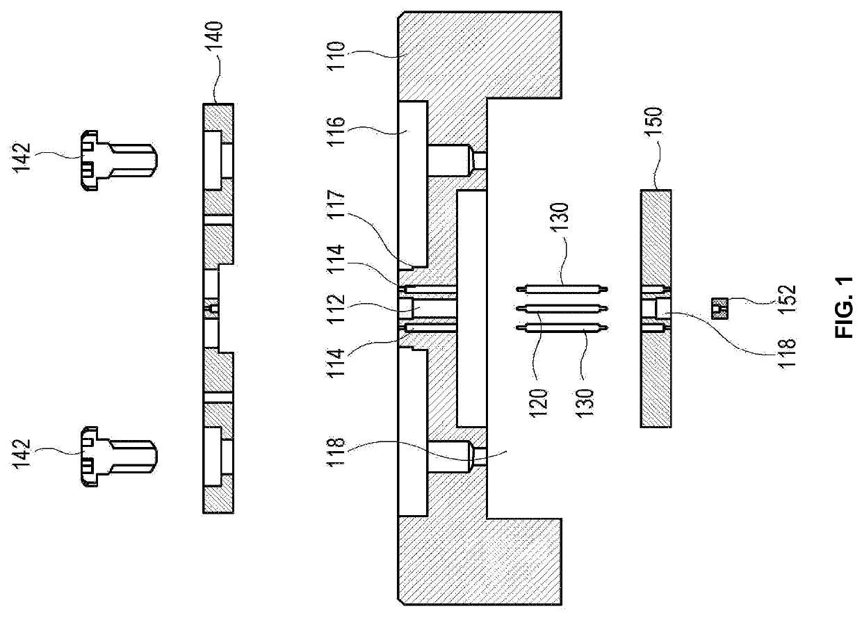
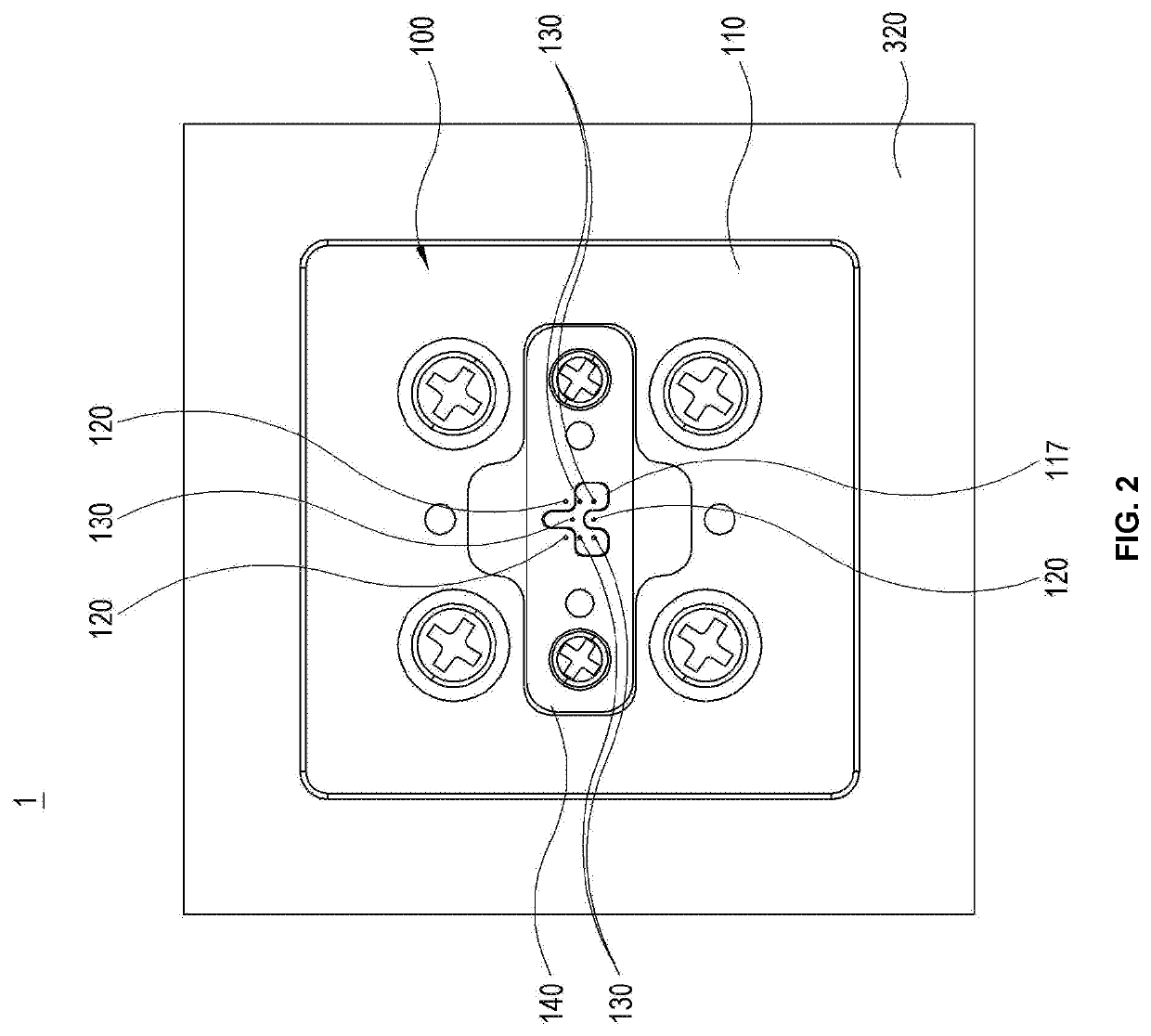
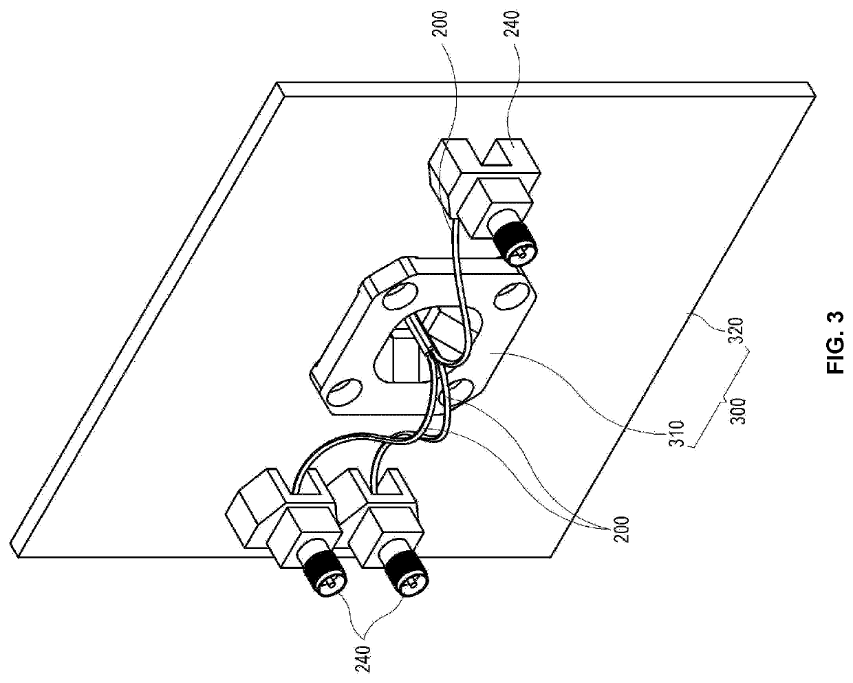
[0021]FIG. 1 is an exploded cross-sectional view of a test socket in the test device 1 according to a first embodiment of the present disclosure, and FIGS. 2 to 6 are respectively a plane view, a bottom perspective view, an exploded perspective view, a cross-sectional view and a partial enlarged cross-sectional view of the test device 1 according to the first embodiment of the present disclosure. As shown therein, the test device 1 includes a test socket 100, a coaxial cable 200, and a cable supporter 300.
[0022]Referring to FIG. 1, the test socket 100 includes a conductive block 110 having at least one signal probe hole 112 and at least one ground probe hole 114; a signal probe 120 contactless-accommodated in the signal probe hole 112; a ground probe 130 contact-accommodated in the ground probe hole 114; an upper supporting member 140 for supportin...
second embodiment
[0034]FIG. 7 is a cross-sectional view of a test device 2 according to the present disclosure. In comparison with the test device 1 described with reference to FIGS. 1 to 6, like numerals refer to like elements, and only different parts will be described.
[0035]As shown therein, the test device 2 includes the test socket 100, the coaxial cable 200, and the cable supporter 300.
[0036]The cable supporter 300 does not include the cable supporting substrate 320 unlike that of the first embodiment, and the signal connector 240 is fastened to the extended plate portion 316 instead of the cable supporting substrate 320.
[0037]In the test device according to the present disclosure, the signal probe supported in the conductive block is in direct contact with the core wire of the coaxial cable, thereby certainly blocking out the noise between the signal lines at a side of an test circuit board and improving the transmission characteristics of the test signal. Thus, the test device according to t...
PUM
 Abstract
Description
Claims
Application Information
 - R&D
- Intellectual Property
- Life Sciences
- Materials
- Tech Scout
- Unparalleled Data Quality
- Higher Quality Content
- 60% Fewer Hallucinations
Browse by: Latest US Patents, China's latest patents, Technical Efficacy Thesaurus, Application Domain, Technology Topic, Popular Technical Reports.
© 2025 PatSnap. All rights reserved.Legal|Privacy policy|Modern Slavery Act Transparency Statement|Sitemap|About US| Contact US: help@patsnap.com


