
Insulating member, stator of rotary electric machine, and rotary electric machine

a technology of rotary electric machines and stators, which is applied in the direction of applying solid insulation, transportation and packaging, windings, etc., can solve the problem of increasing manufacturing costs

Active Publication Date: 2020-07-16
HONDA MOTOR CO LTD +1
View PDF0 Cites 7 Cited by
  • Summary
  • Abstract
  • Description
  • Claims
  • Application Information

AI Technical Summary

Benefits of technology

The invention provides an adhesive layer with an exposed section that prevents the adhesive from peeling off the end edge of a slot when an insulating member is moved in the axial direction of the iron core. This prevents the generation of foreign matter during the manufacturing process of the rotary electric machine.

Problems solved by technology

However, in the method of pouring varnish into the slot, since the varnish poured from one end of the slot flows out from the other end of the slot, the varnish which flows out is discarded, which may increase the manufacturing cost.

Method used


Image

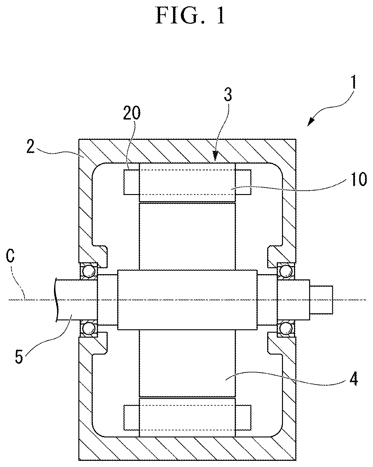
  • Insulating member, stator of rotary electric machine, and rotary electric machine
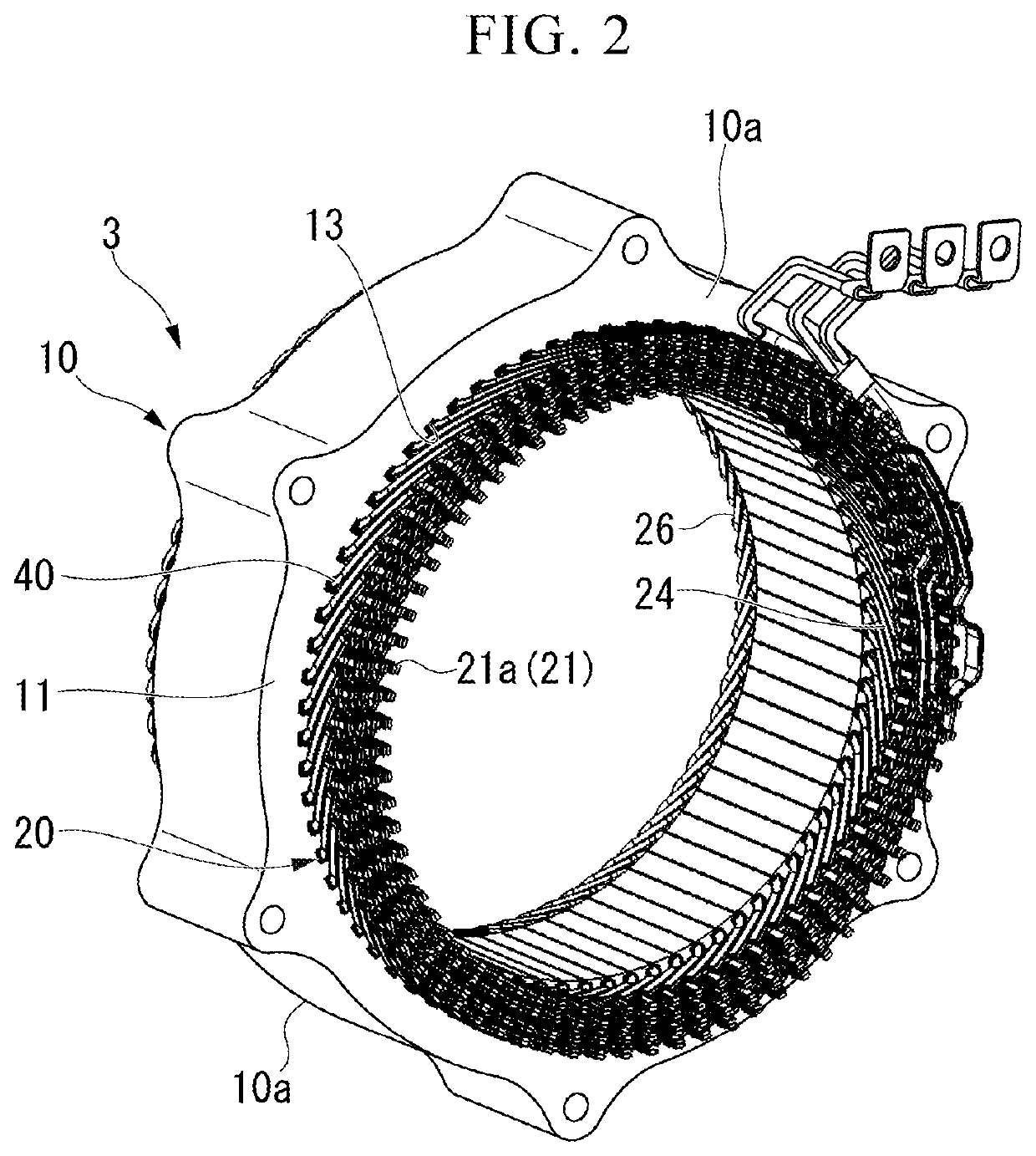
  • Insulating member, stator of rotary electric machine, and rotary electric machine
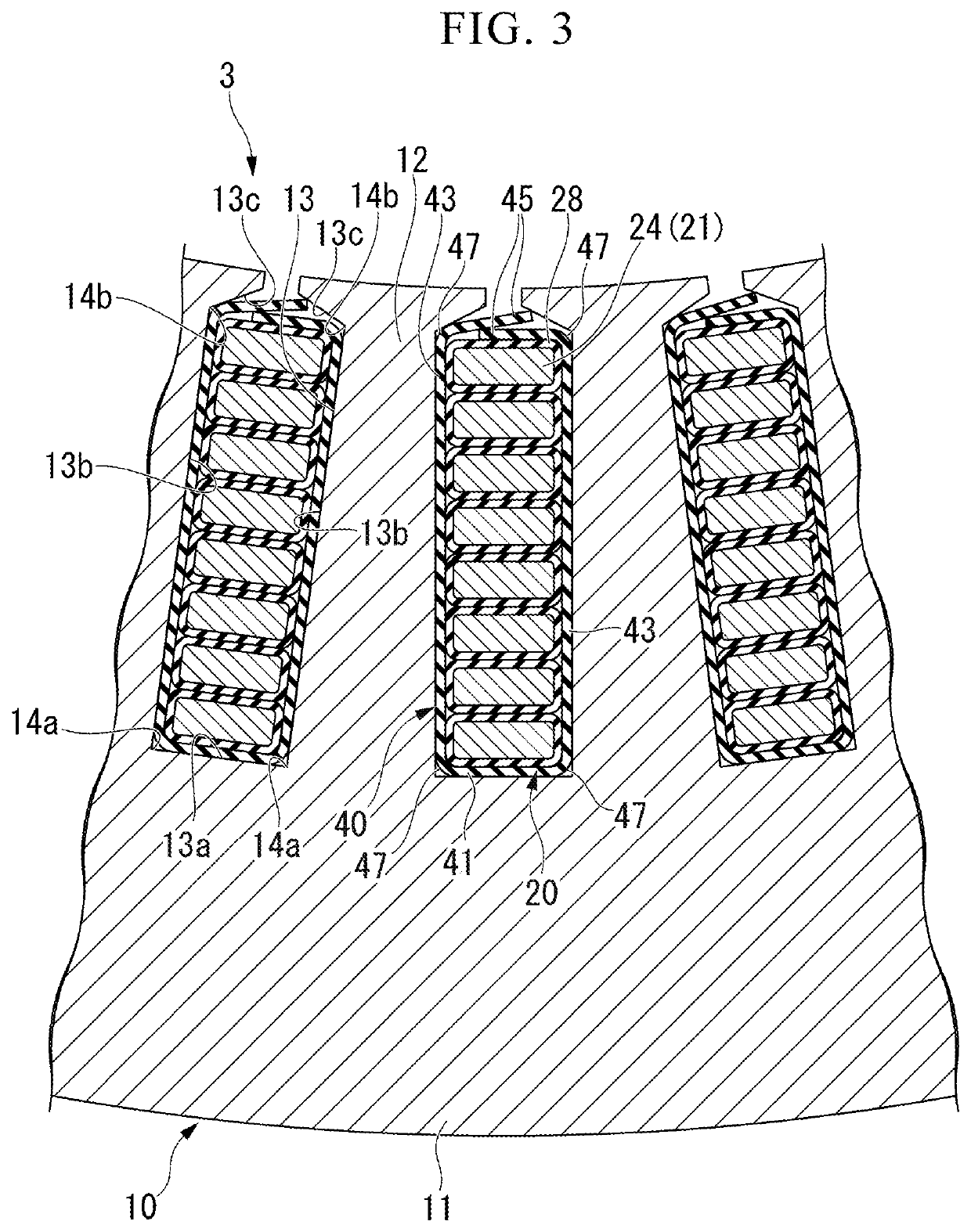
  • Insulating member, stator of rotary electric machine, and rotary electric machine

Examples


first embodiment

Modified Example of First Embodiment

[0065]FIG. 8 is a cross-sectional view showing a part of a stator according to a modified example of the first embodiment. In the first embodiment, the insulating base material 50 is exposed to the outside of the slot insulating paper 40 at the exposed sections 61. On the other hand, the modified example of the first embodiment is different from the first embodiment in that a lubricating layer 63 is provided on the first main surface 50a of the insulating base material 50 at the exposed sections 61. In addition, the same components as those in the first embodiment are denoted by the same reference numerals, and a detailed description thereof will be omitted (the same applies to subsequent embodiments).

[0066]As shown in FIG. 8, a lubricating layer 63 formed of a lubricant is provided on the first main surface 50a of the insulating base material 50 at each exposed section 61. As the lubricant, for example, a resin material having a smaller frictiona...

second embodiment

[0068]FIG. 9 is a cross-sectional view showing a part of a stator according to a modified example of the first embodiment. In the first embodiment, the slot bottom surface 13a of the slot 13 is formed in a planar shape. On the other hand, the second embodiment is different from the first embodiment in that a slot bottom surface 113a of a slot 113 is formed in a concave curved shape.

[0069]As shown in FIG. 9, the slot 113 is formed to be elongated in the radial direction when viewed in the axial direction. The slot 113 has a rectangular shape having a major axis in the radial direction. An inner surface (a slot forming surface) of a stator core 110 surrounding the slot 113 includes a slot bottom surface (a first slot surface or a first slot forming surface) 113a which faces inward in the radial direction, and a pair of slot side surfaces (second slot surfaces or second slot forming surfaces) 113b which extend radially inward from both circumferential end portions of the slot bottom su...


PUM


Abstract

An insulating paper (40) is inserted into a slot (13) of a stator core (10) of a rotary electric machine and insulates between the stator core (10) and a stator coil (20) disposed in the slot (13). An insulating member (40) comprises a sheet-shaped insulating base material (50), and a first adhesive layer (60A) which is provided on a first surface (50a) of the insulating base material (50) and which is formed of an adhesive. The first adhesive layer (60A) is provided with an exposed section (61) which extends in the axial direction of the stator core (10) and in which the insulating base material (50) is exposed from the adhesive.

Description

CROSS REFERENCES TO RELATED APPLICATIONS[0001]This application is a continuation of U.S. application Ser. No. 16 / 477,272, which is the National Stage of International Application No. PCT / JP2018 / 000781, filed Jan. 15, 2018 which claims priority under 35 U.S.C. § 119 to Japanese Patent Application No. 2017-005106, filed Jun. 16, 2017. The contents of these applications are incorporated herein by reference in their entirety.TECHNICAL FIELD[0002]The present invention relates to an insulating member, a stator of a rotary electric machine, and a rotary electric machine.[0003]Priority is claimed on Japanese Patent Application No. 2017-005106, filed Jan. 16, 2017, the content of which is incorporated herein by reference.BACKGROUND ART[0004]A rotary electric machine having a stator and a rotor is mounted in a vehicle such as an electric car or a hybrid car. Teeth of the stator extending in a radial direction thereof are provided on a stator core (iron core) of the stator. Slots through which...

Claims


Application Information

Patent Timeline
Patent Type & Authority Applications(United States)
IPC IPC(8): H02K15/10
CPCH02K15/10H02K3/345Y02T10/64
Inventor YAMAGUCHI, TADASHILEI, MINGOGINO, SHOHEI
Owner HONDA MOTOR CO LTD
Learn More