Rotating Electric Machine
a technology of rotating electric machines and electric motors, which is applied in the direction of dynamo-electric machines, electrical devices, windings, etc., can solve the problems of increasing the frequency of partial discharge and so as to reduce the thickness of main insulation, reduce the amount of charge discharge, and avoid the effect of insulating paper flapping
- Summary
- Abstract
- Description
- Claims
- Application Information
AI Technical Summary
Benefits of technology
Problems solved by technology
Method used
Image

Examples
example 1
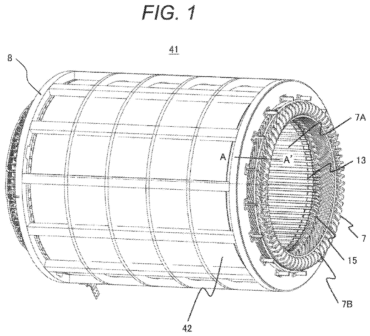
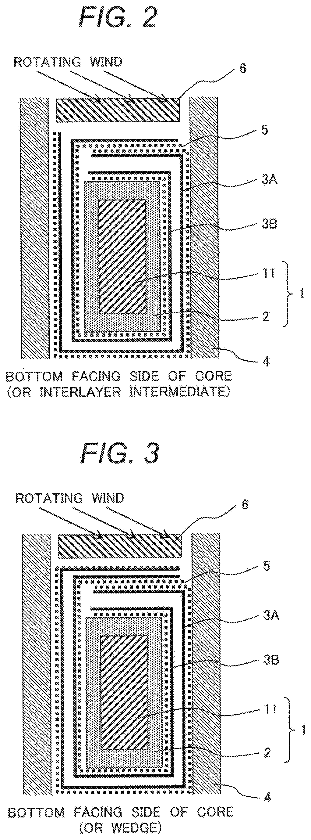
[0031]A rotating electric machine of Example 1 is described with reference to FIG. 1 and FIG. 2. FIG. 1 is an overall perspective view depicting a stator 41 of the rotating electric machine and is common for all examples. In addition, FIG. 2 is a longitudinal sectional view depicting a part of a stator coil in the present example.
[0032]The stator 41 of the rotating electric machine is usually comprised of a stator core 42 supported on a rotating shaft (not depicted) and stator windings (not depicted) situated on the stator core 42.
[0033]The stator core 42 is made of plural thin magnetic steel plates laminated in an axial direction and generally comprised of plural slots 4 formed on the inside of the stator core 42, extending axially and spaced circumferentially at given intervals, stator coils 1 situated inside the plural slots 4, a stator frame 8 supporting the outside of the stator core 42, end plates, not depicted, which are fixed to axially both ends of the stator frame 8, and b...
example 2
[0047]A rotating electric machine of Example 2 is described with reference to FIG. 3. FIG. 3 is a longitudinal sectional view depicting a part of a stator coil in the present example.
[0048]While, in the stator coil in Example 1 (FIG. 2), the insulating paper sheet 3A (first insulating paper sheet) and the insulating paper sheet 3B (second insulating paper sheet) are overlapped near the wedge 6 and brought into contact with each other via the semiconductor layers 5, the present example differs in that the insulating paper sheet 3A (first insulating paper sheet) under (inward of) the wedge 6 is not brought into contact with the insulating paper sheet 3B (second insulating paper sheet) that lies on the inward side of it and nearest to it, as depicted in FIG. 3.
[0049]The present example provides a structure below that is only applicable to a unidirectional rotating electric machine. By orienting a folding line (fold edge) of the insulating paper sheet 3A (first insulating paper sheet) i...
example 3
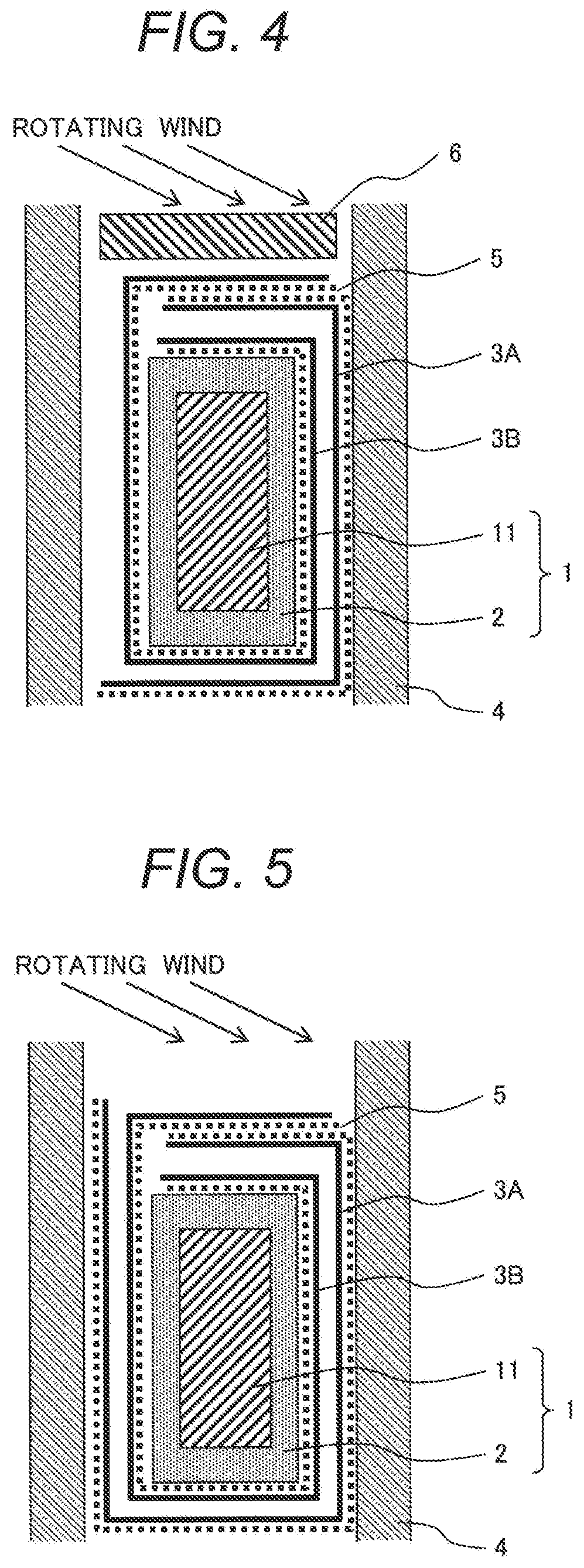
[0052]A rotating electric machine of Example 3 is described with reference to FIG. 4. FIG. 4 is a longitudinal sectional view depicting a part of a stator coil in the present example.
[0053]The stator coil in the present example differs from the stator coil in Example 1 (FIG. 2) in that only one sheet (one fold) of insulating paper 3 lies near one inside (left) of the slot 4, as depicted in FIG. 4.
[0054]In a structure in the present example depicted in FIG. 4, while electric conduction is provided via the semiconductive layers 5 between the stator coil 1 and the slot core 4, a space for one sheet of insulation paper can be saved if there is less allowance for inserting the stator coil 1 and, therefore, it becomes easy to insert the stator coil 1 into the slot core 4.
PUM
 Abstract
Description
Claims
Application Information
 - R&D
- Intellectual Property
- Life Sciences
- Materials
- Tech Scout
- Unparalleled Data Quality
- Higher Quality Content
- 60% Fewer Hallucinations
Browse by: Latest US Patents, China's latest patents, Technical Efficacy Thesaurus, Application Domain, Technology Topic, Popular Technical Reports.
© 2025 PatSnap. All rights reserved.Legal|Privacy policy|Modern Slavery Act Transparency Statement|Sitemap|About US| Contact US: help@patsnap.com