
Rubber Edge Seal Retention Device

a rubber edge and sealing technology, applied in the direction of door arrangement, railway components, transportation and packaging, etc., can solve the problems of not providing optimal, difficult to obtain consistent and accurate bending angles and lengths of wings, and not completely filling, etc., to achieve excellent sealing performance, weight loss, and reduce the effect of weight loss

Active Publication Date: 2020-07-02
WESTINGHOUSE AIR BRAKE TECH CORP
View PDF0 Cites 0 Cited by
  • Summary
  • Abstract
  • Description
  • Claims
  • Application Information

AI Technical Summary

Benefits of technology

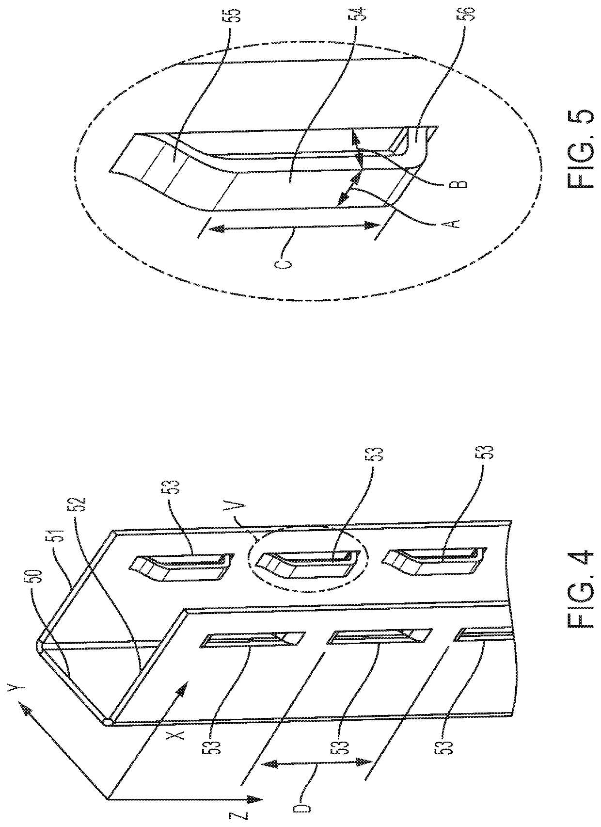
The present disclosure provides a rubber edge seal retention device for transit door panels that is cost-effective and highly repeatable. The device requires only one C-shaped channel member and adds little to no extra weight to the door panel. The device includes a rubber seal made up of a front section and a back section with retention grooves and a wedge, and a metallic C-channel with depressions that match the grooves on the rubber seal. The depressions are created using a punch and die tool or an alternate method of producing the same with substantially similar accuracy. The C-channel can have adjacent depressions or substantially spaced-apart depressions. The rubber seal may have a cavity disposed within the wedge cross section to facilitate insertion of the rubber seal into the C-channel. The device provides sufficient retention to preclude ridership vandalism, while being easily installed. The device may be installed on stainless steel structure door panels used on railcar transit and commuter vehicles.

Problems solved by technology

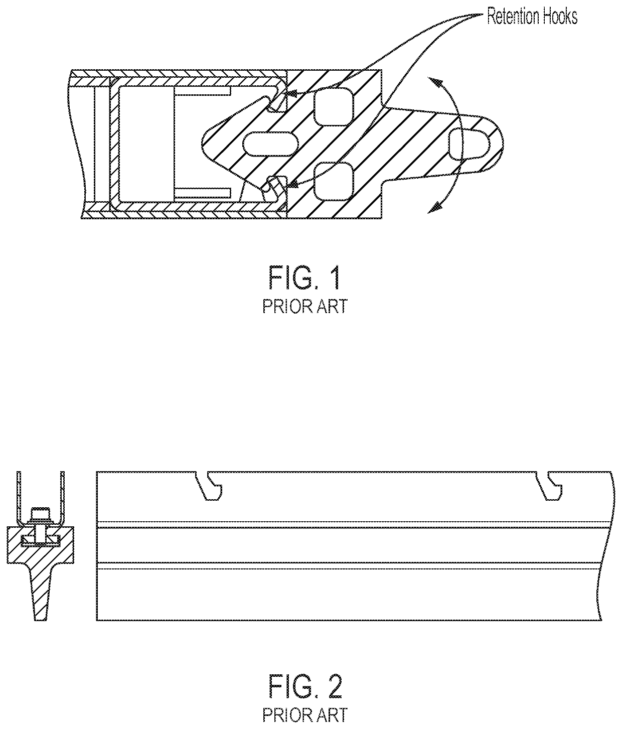
This method, while inexpensive to manufacture, does not provide optimum results because it is difficult to obtain consistent and accurate bending angles and lengths of the wings.
Moreover, the wings do not entirely fill the mating groove of the rubber seal member.
This solution provides good seal retention but has the disadvantage of adding to the overall weight of and cost of the door panel, including substantial additional labor for assembly, due to the need for the additional seal carrier and pins inserted into the first C-shaped channel member on the door panel edge.
The cost of the seal carrier is also increased when the door panel profile is curved.

Method used


Image

  • Rubber Edge Seal Retention Device
  • Rubber Edge Seal Retention Device
  • Rubber Edge Seal Retention Device

Examples


Embodiment Construction

[0020]For purposes of the description hereinafter, the terms “end”, “upper”, “lower”, “right”, “left”, “vertical”, “horizontal”, “top”, “bottom”, “lateral”, “longitudinal”, and derivatives thereof shall relate to the invention as it is oriented in the drawing figures. However, it is to be understood that the invention may assume various alternative variations and step sequences, except where expressly specified to the contrary. It is also to be understood that the specific devices and processes illustrated in the attached drawings and described in the following specification are simply exemplary embodiments or aspects of the invention. Hence, specific dimensions and other physical characteristics related to the embodiments or aspects disclosed herein are not to be considered as limiting.

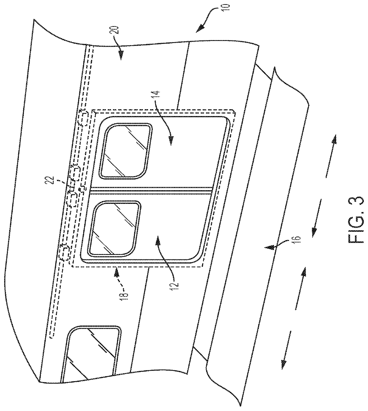
[0021]With reference to FIG. 3, a transit vehicle 10, such as a subway car, trolley car, other rail transit vehicle, or similar vehicle, is shown according to an example of the present disclosure. Th...


PUM


Abstract

A sealing system for an openable panel on a vehicle includes a channel member disposed on the openable panel and extending along a longitudinal axis and a seal member fastened to the channel member. The channel member includes two side portions extending parallel to each other and a recess defined between the two side portions. A plurality of depressions are defined in the side portions and extend along the longitudinal axis and into the recess. The seal member includes a proximal portion disposed within the recess and a distal portion extending away from the channel member. The proximal portion of the seal member has grooves defined on opposing sides thereof. The plurality of depressions on each side portion of the channel are received in a respective groove on the seal member to fasten the seal member to the channel member.

Description

BACKGROUND OF THE INVENTIONField of the Invention[0001]The present invention relates generally to sealing assemblies on door panels for transit vehicles, such as subway and commuter railcars. More particularly, the present invention relates to a sealing assembly in which a sealing member is assembled within a C-shaped channel member.Description of Related Art[0002]Several designs of transit door panels fitted with rubber edge seals have been described in the prior art and utilized on transit railcars. In several of these designs, the door panel structure is made from extruded profiles, most frequently aluminum profiles. The extruded profile easily lends itself to providing a continuous built-in retention feature for the rubber seal member. One example of such a built-in retention feature for the rubber seal member applied to the extruded profile is disclosed in United States Patent Application Publication No. 2017 / 0305247, which is hereby incorporated by reference in its entirety.[0...

Claims


Application Information

Patent Timeline
IPC IPC(8): B61D19/00
CPCB61D19/005
Inventor NICOLE, MARTIN
Owner WESTINGHOUSE AIR BRAKE TECH CORP
Learn More