
Flow Monitoring And Error Detection In A Mobile Liquid Agricultural Product Applicator

Active Publication Date: 2020-06-25
BLUE LEAF I P
View PDF4 Cites 14 Cited by
  • Summary
  • Abstract
  • Description
  • Claims
  • Application Information

AI Technical Summary

Benefits of technology

The present invention is about monitoring and detecting errors in a mobile liquid agricultural product applicator. It uses pressure sensors to measure the pressure drop across a nozzle to determine if there is a problem with the flow of liquid. The system can detect errors on a per-section basis, which makes it easier to identify which part of the system is causing the problem. By adjusting the control valve of the affected section, the system can fix any issues quickly. Overall, the invention improves the accuracy and efficiency of the liquid agricultural product applicator by identifying and addressing potential flow blockages and components failures in real-time.

Problems solved by technology

Application rate adjustments can be made during an initial liquid calibration process, which can be time-consuming.
Although overall application rate can be adjusted, detecting flow-compromising blockages at specific locations during use can be challenging because of the way(s) that system performance is typically monitored.
Although this approach may indicate overall acceptability of flow rate and pressure values within the manifold assembly, at times, such acceptable values may not be indicative of appropriate product delivery characteristics at a per-row or even per-section basis.
Even if unacceptable flow and / or pressure values are identified in the manifold assembly, these systems are typically unable able to provide feedback or identify which rows are not receiving the correct amount of product that would help diagnose potential blockage or component failure locations within the system.
However, turbine-style flow meters have moving parts that can wear over time and can accumulate fertilizer or debris, which compromises their performance.

Method used


Image

  • Flow Monitoring And Error Detection In A Mobile Liquid Agricultural Product Applicator
  • Flow Monitoring And Error Detection In A Mobile Liquid Agricultural Product Applicator
  • Flow Monitoring And Error Detection In A Mobile Liquid Agricultural Product Applicator

Examples


Embodiment Construction

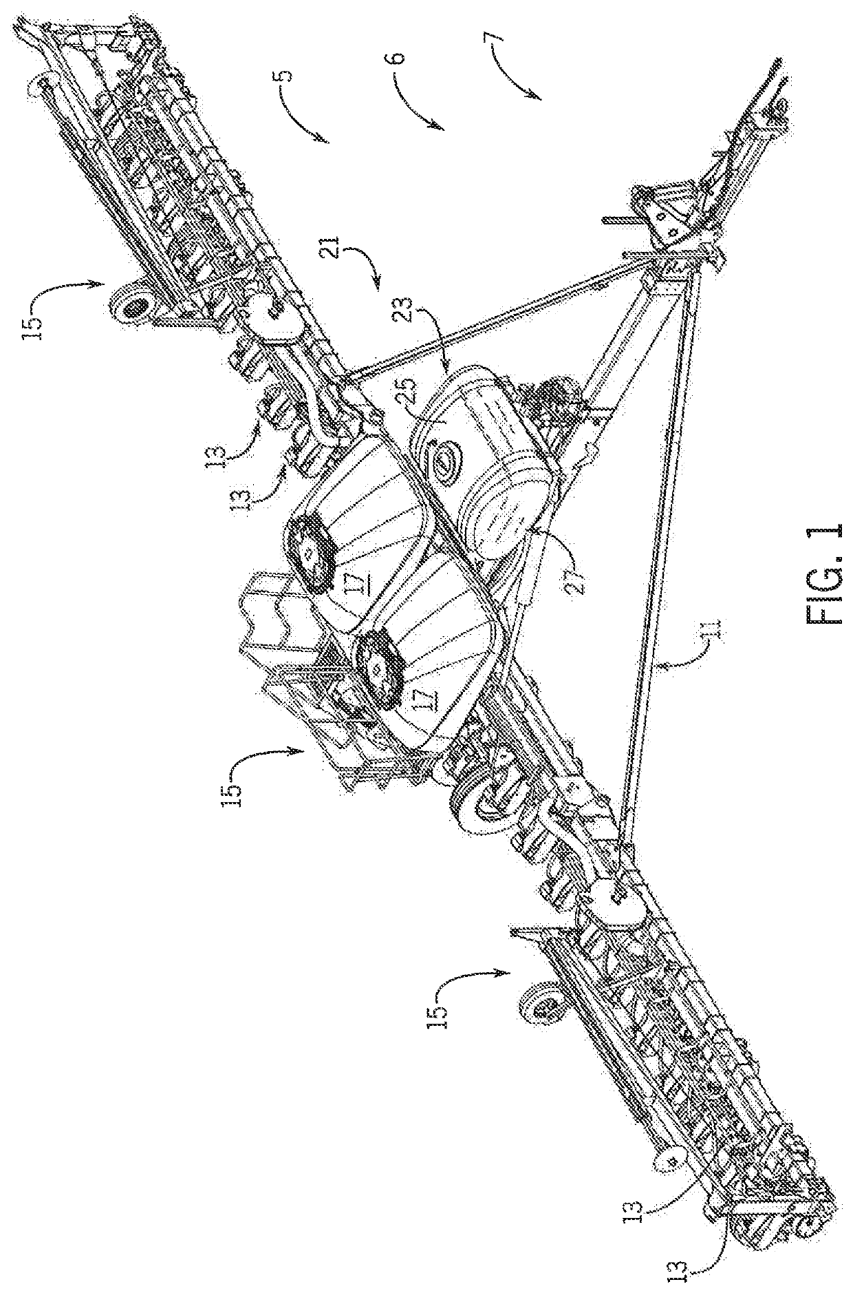
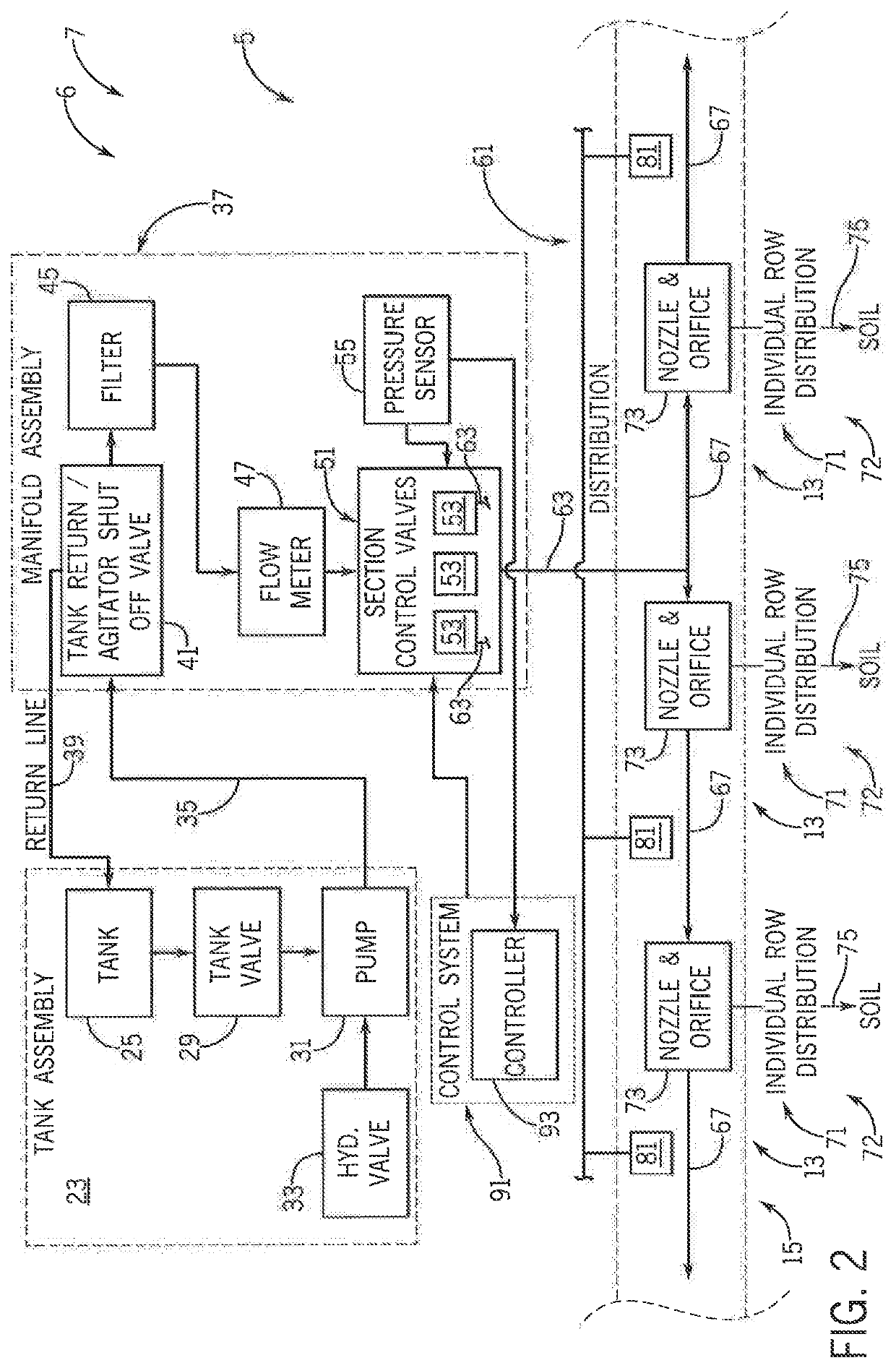
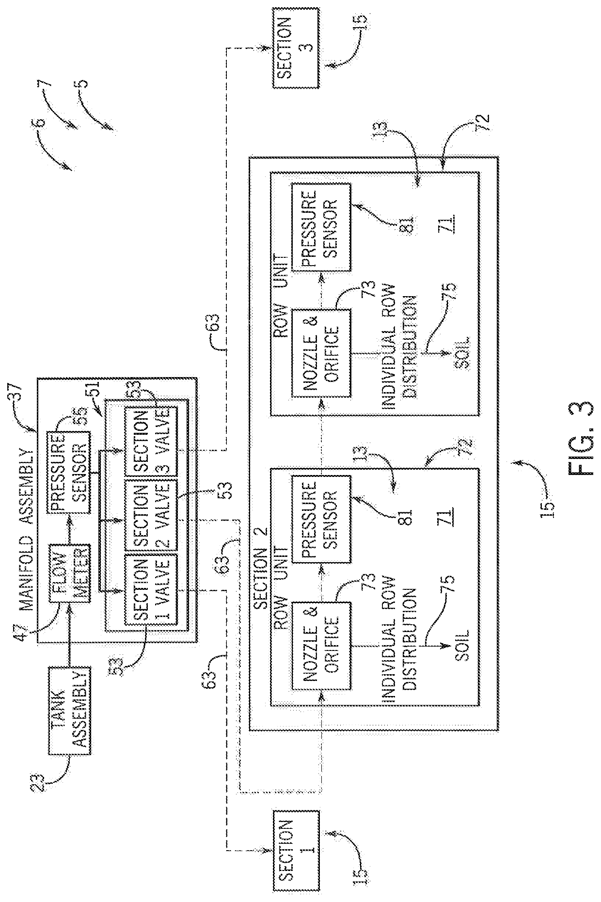
[0020]Referring now to the drawings and specifically to FIG. 1, an error detection and flow monitoring system is shown as system 5 that can provide feedback to identify locations of potential blockage or component failure and can also expedite initial liquid flow calibration procedures.

[0021]System 5 is incorporated in an implement 6 with a liquid fertilizer system as a mobile liquid agricultural product applicator. Implement 6 may be, for example, a planter, a seeder, a strip-till tool, and a side dress toolbar or other fertilizer applicator(s). The exemplary implement 6 represented here is shown as a planter 7, which may be one of the EARLY RISER® series planters available from Case IH and is typically pulled by a traction device such as a tractor. A frame 11 of the planter 7 supports multiple row units 13 that are substantially identical within planter sections 15. Planter sections 15 are shown here as a center section with a pair of wing sections or outer sections arranged trans...


PUM


Abstract

An error detection and flow rate monitoring system of a liquid fertilizer distribution system of an agricultural implement that can provide feedback to identify compromised flow states in the system and corresponding locations of potential blockage or component failure. The system may include pressure sensors that may be evaluated in pairs or otherwise analyzed comparatively to determine flow rate or other characteristics through nozzle assemblies. The pressure sensors may be mounted in the wet boom between the rows. A control system compares the pressure values before and after each row to determine the pressure drop across its nozzle assembly and may further use the pressure drop values to determine flow or application rates and corresponding errors in the pressure drop, flow rate, and application rate compared to their acceptable values and may provide feedback to identify a specific location(s) of potential blockage or flow-control component failure.

Description

FIELD OF THE INVENTION[0001]The subject matter disclosed herein relates generally to liquid fertilizer distribution systems of agricultural implements such as row-crop planters, seeders, strip-till tools, side dress toolbars, fertilizer applicators, and the like and, in particular, to a system for detecting error and monitoring flow rate of a liquid fertilizer distribution system of an agricultural implement to facilitate detecting system blockages and expedite initial liquid flow calibration.BACKGROUND OF THE INVENTION[0002]Modern farming practices strive to increase yields of agricultural fields. Technological advances of planters allow for better agronomic characteristics at the time of planting, such as providing more accurate seed depth, improved uniformity of seed depth across the planter, improved accuracy of in-row seed spacing, and improvements in making nutrients readily available to seeds. Modern farming practices also strive to minimize operating expenses. Ways of reduci...

Claims


Application Information

Patent Timeline
IPC IPC(8): A01C21/00B05B12/00B05B1/20A01C23/04A01B76/00
CPCA01C21/00B05B12/008B05B1/20A01B76/00A01C23/047A01M7/0089A01C7/06A01C23/007B05B9/007B05B9/0416B05B9/0423B05B12/088
Inventor SCHOENY, CHRISTOPHERSTANHOPE, TREVOR
Owner BLUE LEAF I P
Learn More