
Surgical instrument detection system and computer program

Active Publication Date: 2020-06-18
EIZO
View PDF0 Cites 5 Cited by
  • Summary
  • Abstract
  • Description
  • Claims
  • Application Information

AI Technical Summary

Benefits of technology

The patent text describes a system that can detect different types of surgical instruments without needing to apply a special code to them. This makes it easier to identify the instruments and their numbers.

Problems solved by technology

It is thus difficult even for an experienced nurse to accurately distinguish the kinds of surgical instruments by visual observation.

Method used


Image

  • Surgical instrument detection system and computer program
  • Surgical instrument detection system and computer program
  • Surgical instrument detection system and computer program

Examples


embodiments

[0048]A detailed description is given below to embodiments of the present invention with reference to the drawings. An identical reference sign is given to identical or equivalent parts in the drawings to omit repetitive descriptions. To facilitate the understanding of the description, the drawings referred below may be illustrated in a simplified or schematic configuration or may have omitted components. The scale ratio of the components illustrated in each drawing does not have to reflect the actual scale ratio.

first embodiment

[0049]The first embodiment is described below.

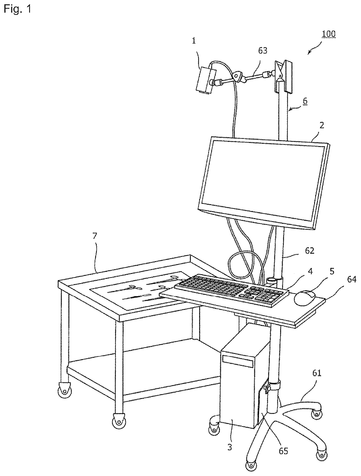
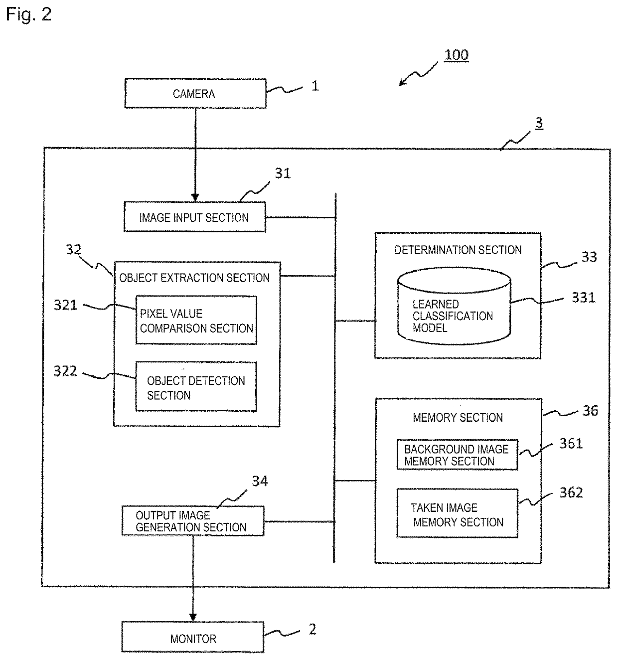
[0050]FIG. 1 illustrates an overview of the hardware configuration of a surgical instrument detection system according to the first embodiment. A surgical instrument detection system 100 according to the present embodiment is a small steel article detection system to particularly detect small steel articles among surgical instruments and includes, as illustrated in FIG. 1, a camera 1, a monitor 2, a computer 3, a keyboard 4, and a mouse 5.

[0051]The camera 1, the monitor 2, the keyboard 4, and the mouse 5 are connected to the computer 3. Although FIG. 1 exemplifies a configuration provided with the keyboard 4 and the mouse 5, it is possible to omit the keyboard 4 and the mouse 5 by using a monitor allowing touch screen input. Alternatively, a computer may be used that includes a microphone instead of the keyboard 4 and the mouse 5 to accept directions from a user by voice input.

[0052]The camera 1, the monitor 2, and the computer 3 are mou...

second embodiment

[0068]A surgical instrument detection system 200 according to the second embodiment has, in addition to the surgical instrument detection system according to the first embodiment, a function of checking whether all small steel articles are complete after surgery.

[0069]As illustrated in FIG. 7, the surgical instrument detection system 200 thus further includes a comparison section 35. In the present embodiment, after surgery, collected small steel articles are placed on the instrument placement table 7 to be photographed with the camera 1 and, similar to the first embodiment, the kinds and number of the small steel articles included in the taken image are detected. The comparison section 35 compares the kinds and number of small steel articles before and after surgery to detect the excess or deficiency.

[0070]In the surgical instrument detection system 200, the memory section 36 further includes a prescribed number memory section 363 to memorize the kinds and number of small steel art...


PUM


Abstract

A surgical instrument detection system is provided that can determine the kinds of surgical instruments without special processing, such as application of an optically readable symbol, to the surgical instruments. A surgical instrument detection system 100 includes: an image input section 31 to input an image taken by a camera 1; an object extraction section 32 to clip an object image of a small steel article from the input image; a determination section 33 to input the object image to a learned classification model 331 and determine a kind of the small steel article based on features included in the object image; and an output image generation section 34 to generate an image representing the result of determination by the determination section and output such image to a monitor 2.

Description

TECHNICAL FIELD[0001]The present invention relates to a system to detect a surgical instrument used in surgery and the like.BACKGROUND ART[0002]Many surgical instruments, such as forceps and tweezers, are used in surgery. Since leaving a surgical instrument in the patient's body during surgery is medical malpractice that should not occur, it is thoroughly ensured that the kind and number of surgical instruments are counted before surgery and whether all surgical instruments are complete is checked after surgery.[0003]However, surgical instruments come in a wide variety of kinds and many of them look very alike only with a slight difference in shape and size. It is thus difficult even for an experienced nurse to accurately distinguish the kinds of surgical instruments by visual observation.[0004]A surgical appliance preparation system is conventionally proposed that can identify the kinds of surgical appliances (including small steel articles) using optically readable symbols, such a...

Claims


Application Information

Patent Timeline
IPC IPC(8): G06K9/62A61B34/00A61B34/20G06K9/34G06K9/46G06V10/44G06V10/56
CPCG06K9/4652G06K9/342A61B2034/2055G06K9/6267G06K2209/057G06K9/6202A61B17/28A61B2034/2065A61B34/25A61B34/20G06T7/00G06V10/44G06V10/56G06V10/751G06V2201/034A61B90/90A61B90/08G06T7/0008G06T7/11A61B2090/0805G06V20/00G06F18/24
Inventor KATAYAMA, TAKUYASUGII, NOBUAKI
Owner EIZO
Learn More