Eureka AIR delivers breakthrough ideas for toughest innovation challenges, trusted by R&D personnel around the world.

Positioning device

a positioning device and positioning technology, applied in the direction of cleaning process and apparatus, program-controlled manipulators, cleaning using liquids, etc., can solve the problems of inconvenient positioning, multiple deployment tools, and large design time, and achieve the effect of stiffening the bladder

Pending Publication Date: 2020-06-18
ROLLS ROYCE PLC
View PDF4 Cites 3 Cited by
  • Summary
  • Abstract
  • Description
  • Claims
  • Application Information

AI Technical Summary

Benefits of technology

The invention provides a flexible deployment device that can be accurately positioned at different locations without needing a specific design for each location. The device uses a soft robotics fixturing element to resist reaction forces during use. The fixturing element is made up of inflatable bladders, particle filled bladders, dielectric elastomers, and shape memory alloys. These actuators help brace the device against the cavity wall or fine adjust its position. The fixturing element and the tool are affixed together to counteract the reaction forces generated during operation. Additionally, the fixturing element has an outer coating or surface topology to increase friction with the cavity wall.

Problems solved by technology

This requires significant design time and multiple deployment tools are required for each engine.
Articulating deployment devices can be steered to and deployed in more than one engine region but they are not useful where the tool generates a reaction force.
For example, where the tool is a fluid jet or a media blaster, the reaction force can cause unwanted movement of the tool (because the deployment device is not rigid) and can cause it to be incorrectly positioned.

Method used


Image

  • Positioning device
  • Positioning device

Examples


Embodiment Construction

[0051]Aspects and embodiments of the present disclosure will now be discussed with reference to the corresponding drawings. Other aspects and embodiments will be apparent to those skilled in the art.

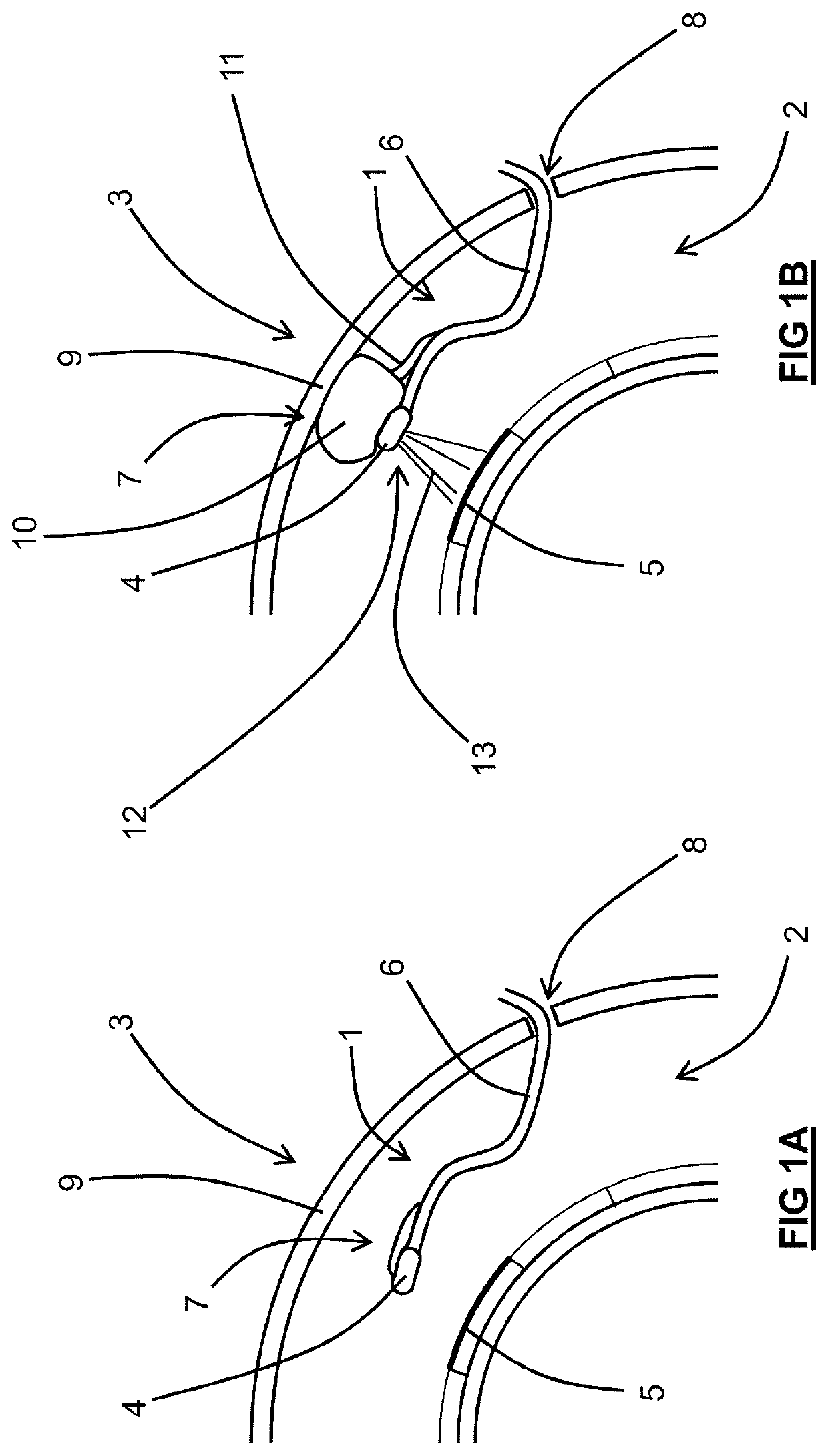
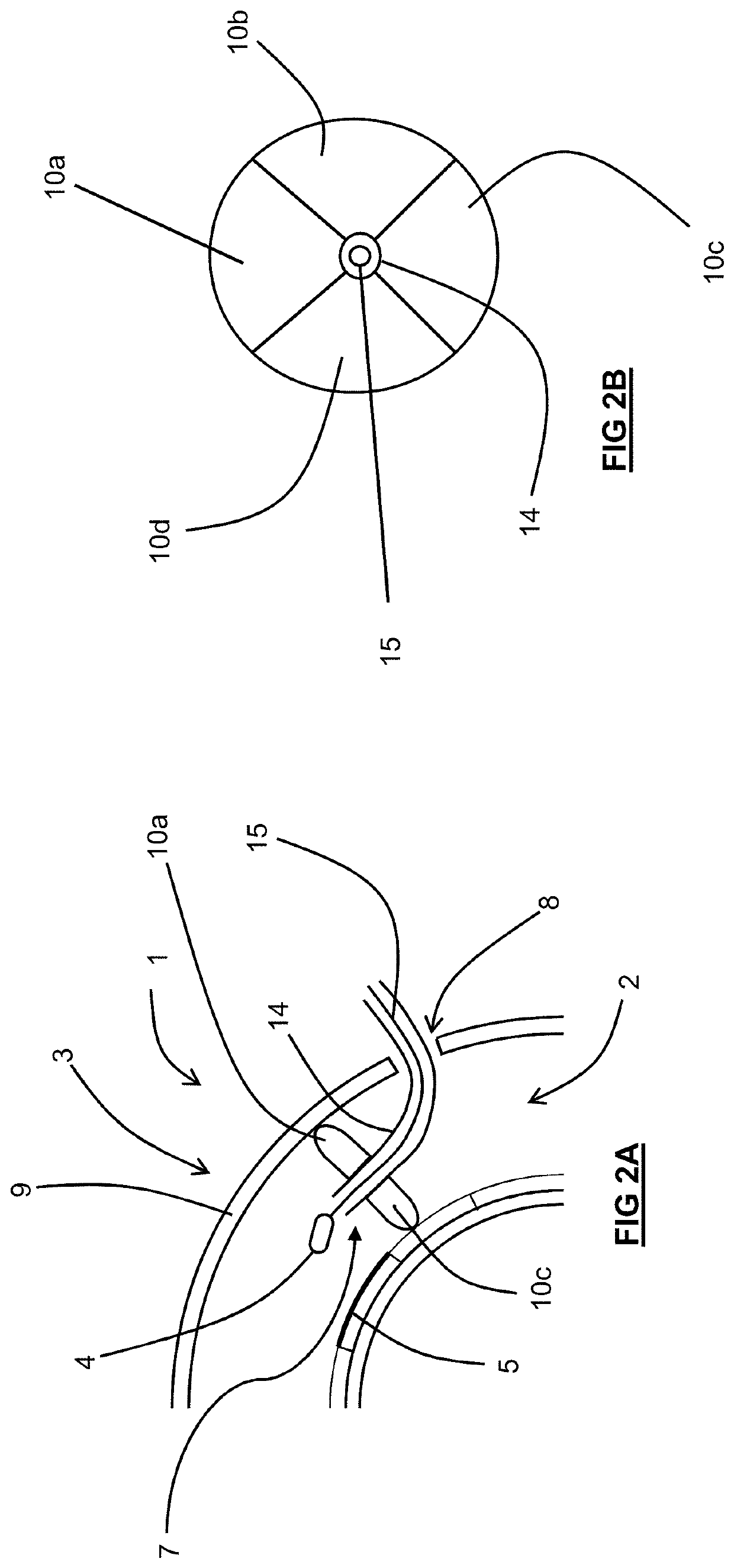
[0052]FIG. 1A shows an embodiment of the device 1 being deployed in the cavity 2 of a gas turbine engine 3. In this case, the device 1 is being used for positioning and using a tool 4 within the cavity 2 for the purpose of repairing a combustor tile with a delaminated coating 5.

[0053]The device 1 comprises a flexible robotic deployment arm 6 (having multiple degrees of freedom) carrying the tool 4. The device further comprises a soft robotic fixturing element 7 disposed at an end of the deployment arm 6 that is adjustable between a contracted (deployment) configuration and an expanded (bracing) configuration. In FIG. 1A the fixturing element 7 is in the contracted deployment configuration. In this configuration, the fixturing element 7 is able to pass through a bore 8 formed in a wall 9 ...


PUM


Abstract

A positioning device for positioning and using a tool within a cavity having a cavity wall. The device comprises a flexible deployment device / arm carrying the tool. The deployment device / arm further comprises a soft robotics fixturing element adjustable between a contracted deployment configuration during positioning of the tool to an expanded bracing configuration for abutment with the cavity wall during use of the tool.

Description

CROSS-REFERENCE TO RELATED APPLICATIONS[0001]This specification is based upon and claims the benefit of priority from United Kingdom patent application number GB 1820507.0 filed on Dec. 17 2018, the entire contents of which are incorporated herein by reference.BACKGROUNDField of the Disclosure[0002]The present disclosure relates to a positioning device. In particular, the present disclosure relates to a positioning device for locating an end effector (tool) in a cavity e.g. in a cavity within a gas turbine engine.Description of the Related Art[0003]There is often a need to carry out inspection, evaluation or maintenance of on-wing gas turbine engines. It is known to perform an on-wing borescope inspection of blades / stators in the front section of the engine whilst rotating the engine shaft (e.g. the intermediate pressure (IP) shaft) using a turning tool. It is also known to effect on-wing cleaning of combustor tiles using a spray cleaning / abrading tool.[0004]These tools are typicall...

Claims


Application Information

Patent Timeline
Patent Type & Authority Applications(United States)
IPC IPC(8): F15B15/10B25J9/14
CPCF15B15/103B25J9/065B08B3/02B25J9/142B25J18/06B25J9/1075B25J11/00B25J9/10B25J15/0095
Inventor NORTON, ANDREW D.KELL, JAMESDANVERS, THOMAS
Owner ROLLS ROYCE PLC
Why Eureka
Eureka Blog
Learn More