Liquid filter assembly

Active Publication Date: 2020-06-11
DONALDSON CO INC
View PDF0 Cites 0 Cited by
  • Summary
  • Abstract
  • Description
  • Claims
  • Application Information

AI Technical Summary

Benefits of technology

The present invention provides a filter assembly for heavy-duty equipment that has an improved drainage system compared to traditional automotive applications. The assembly has a base that receives a cover with a large drainage orifice, which reduces the required drainage time. The filter element is attached to the cover and is guided and maintained in a predetermined angular orientation when the cover is engaged with the base. The drainage plug has a surface shaped like a cylindrical mantle, and a protrusion on the filter element blocks a catching surface on the base to prevent rotation of the filter element during screwing-on of the cover. These features enable the desired angular orientation of the filter element to be reached and maintained without risking installation difficulties.

Problems solved by technology

The filter element is periodically removed for servicing, for example when it becomes sufficiently occluded to generate an undesirable level of restriction across the filter media, or when a service filter interval has passed.
When the cover and the element are removed, they are lifted up above the level of the inlet and the outlet, and there is a risk that used lubricant leaking out of the cartridge contaminates the clean side (outlet side) of the module, or is spilled or over the equipment, the floor, or the operator.
The inventors have found that despite these measures, the aforementioned contamination and spilling still occur to a certain extent.

Method used


Image

  • Liquid filter assembly
  • Liquid filter assembly
  • Liquid filter assembly

Examples


Embodiment Construction

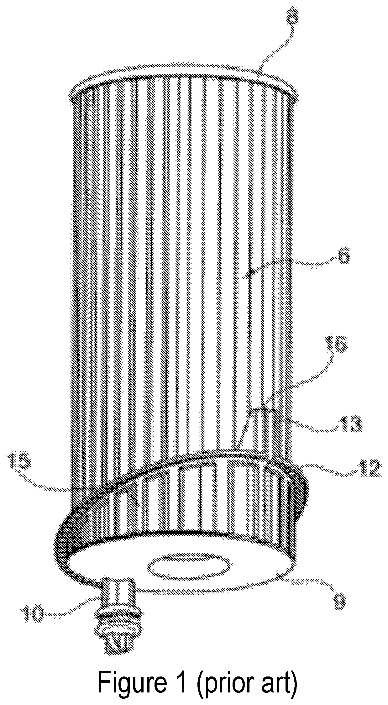
[0049]FIG. 1 illustrates a prior-art filter assembly for hydraulic fluids, in particular an oil filter assembly, as disclosed in DE 10 2013 202 446 A1. It has a separable, substantially cylindrical housing, which comprises a bowl-like lower part and a cover part that can be attached to it, and with a ring-shaped filter element that substantially consists of a filter surface 6 closed onto itself, in particular folded in a star-like manner, and substantially circular end discs 8, 9 that are connected with the ring-shaped edges of the filter surface. The filter element can be axially arranged into the lower part.

[0050]The figure further shows an eccentrically placed axial protrusion 10 on the lower end disc 9 of the filter cartridge, which plugs the drainage orifice when the filter cartridge is inserted in the correct position. When the filter cartridge is partially removed from its operational position, the drainage orifice will be unplugged, allowing the filter housing to be drained ...


PUM

PropertyMeasurementUnit
Angleaaaaaaaaaa
Distanceaaaaaaaaaa

Abstract

The disclosure pertains to a filter assembly comprising a base, a cover, and a cylindrical filter element, the base being adapted to receive the cover with the filter element inserted therein. The base has an outlet orifice with a first sealing zone, and a drainage orifice with a second sealing zone. The filter element comprises an outlet tube with a first sealing element, and a drainage plug with a second sealing element, said outlet tube and said drainage plug being positioned to sealingly engage with said first sealing zone and said second sealing zone, respectively, when the base receives the cover. An axial distance (A) between the first sealing element and the second sealing element is different from an axial distance (B) between an end of the first sealing zone and an end of the second sealing zone facing the filter element. The present disclosure also pertains to a filter element for use in such a filter assembly.

Description

[0001]This application is being filed on Sep. 14, 2017, as a PCT International Patent application and claims the benefit of priority to U.S. Provisional patent application Ser. No. 62 / 394,363, filed Sep. 14, 2016, the entire disclosure of which is incorporated by reference in its entirety.FIELD OF THE INVENTION[0002]The present invention pertains to the field of liquid filter assemblies, in particular lubricant or fuel filter assemblies that contain a filter element for filtering lubricant or fuel used by a hydraulic or mechanical equipment or an engine such as a vehicular internal combustion engine.BACKGROUND[0003]Liquid filter assemblies generally comprise a part that is fixed to the motor vehicle or motorized equipment for which they provide the lubricant filtering function, and a cover that may be separated therefrom to access and replace the filter element. The filter element is periodically removed for servicing, for example when it becomes sufficiently occluded to generate an...

Claims


Application Information

Patent Timeline
IPC IPC(8): B01D35/16B01D35/153B01D35/30B01D29/33
CPCB01D2201/316B01D35/30B01D35/153B01D2201/4023B01D35/16B01D2201/347B01D29/33B01D2201/4092B01D2201/291B01D2201/34B01D2201/4076B01D2201/4046
Inventor GHISU, LUCAVAN DE POEL, GUNTHERHANDZLIK, LUKASZROELS, JOOSTVERBELEN, ERWIN
Owner DONALDSON CO INC
Why Eureka
Try Eureka