Eureka AIR delivers breakthrough ideas for toughest innovation challenges, trusted by R&D personnel around the world.

Rotating machine controller

a technology of rotating machine and controller, which is applied in the direction of electrical steering, dc and ac dynamo-electric motor control, transportation and packaging, etc., can solve the problems of not being able to perform simultaneous control of dc motor and three-phase motor

Active Publication Date: 2020-06-04
DENSO CORP
View PDF0 Cites 4 Cited by
  • Summary
  • Abstract
  • Description
  • Claims
  • Application Information

AI Technical Summary

Benefits of technology

The present invention is about a rotating machine controller that can manage the supply of power to both a multi-phase and a DC rotating machines at the same time. The main technical effect is to provide a more flexible and efficient way to control the power supply for rotating machines.

Problems solved by technology

That is, only one of the DC motor and the three-phase motor is driven at one time, and simultaneous control of the DC motor and the three-phase motor is not performable.

Method used


Image

  • Rotating machine controller
  • Rotating machine controller
  • Rotating machine controller

Examples


first embodiment

[0054]FIG. 7 shows a configuration of the ECU 10 in its entirety, according to a first embodiment of the present disclosure. The first set of three-phase winding 801 of the three-phase motor 800, the U1-phase, V1-phase, and W1-phase winding wires 811, 812, 813, is configured to be connected at a neutral point N1. The second set of three-phase winding 802, the U2-phase, V2-phase, and W2-phase winding wires 821, 822 and 823, is configured to be connected at a neutral point N2. In each phase of the three-phase motor 800, a counter electromotive voltage is generated in proportion to the product of the rotation speed and the sin value of the phase. An electric angle θ of the three-phase motor 800 is detected by a rotation angle sensor.

[0055]The three DC motors 710, 720, 730 are connected at positions between the respective phases of the first set of three-phase winding 801 and the respective phases of the second set of three-phase winding 802 without overlapping, for example, one motor t...

second embodiment

[0132]The second embodiment of the present disclosure is described with reference to FIG. 20. In FIG. 20, the same reference numerals represent the same parts in FIG. 7. In the second embodiment, the first inverter 601 and the second inverter 602 are respectively connected to two independent DC power sources 51 and 52. In addition, smoothing capacitors 53 and 54 are individually provided for input sections of the inverters 601 and 602, respectively. That is, the second embodiment is a so-called “complete duplex system” having a redundant configuration, and other parts other than the connection to the DC power sources 51 and 52 are the same as the first embodiment.

[0133]In such a configuration, the same control as that of the first embodiment is performable. At S31 of FIG. 12 and FIG. 15, when the difference between the input voltages Vin1 and Vin2 of the inverters 601 and 602 is equal to or greater than a predetermined value and it is determined as NO, the control unit 30 does not e...


PUM


Abstract

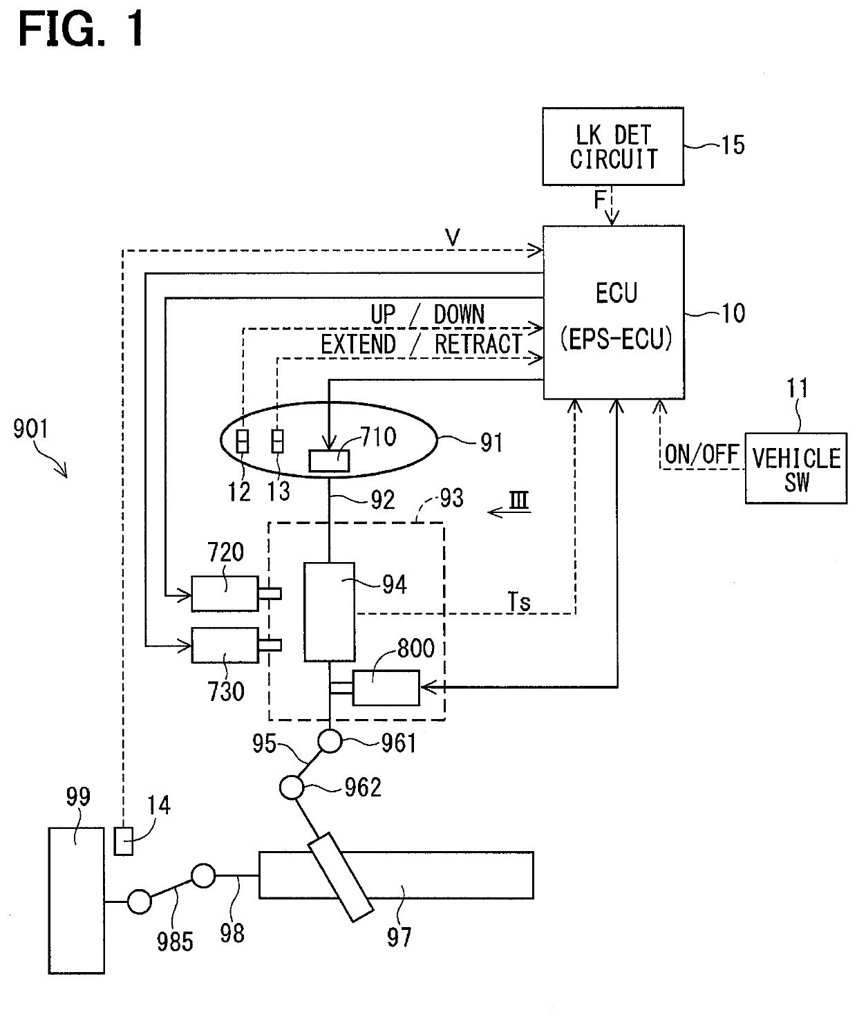
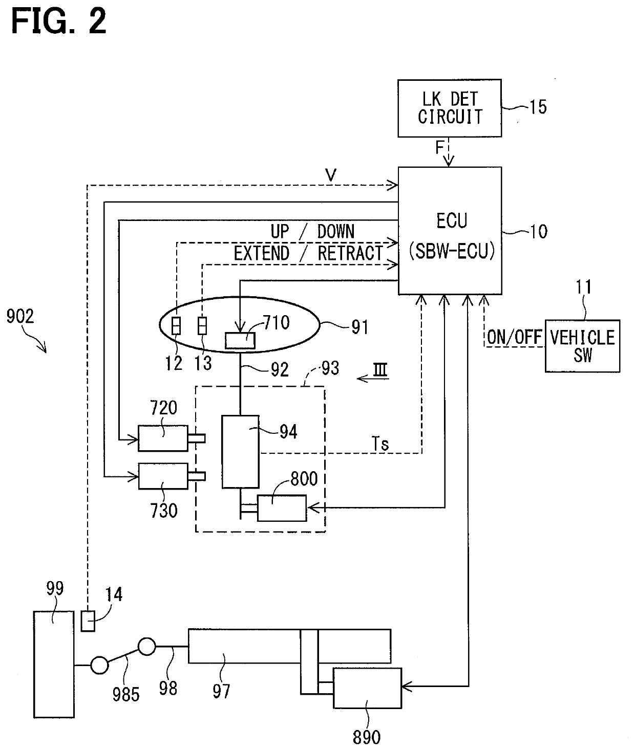
An electronic control unit, for example, a rotating machine controller, is capable of driving one three-phase motor including a first set of three-phase winding and a second set of three-phase winding and one to three direct current motors. The direct current motor is connected to a position between one phase of the first set of three-phase winding and one phase of the second set of three-phase winding without redundancy. Inverters convert a direct current electric power to a three-phase alternating current electric power by an operation of bridge-connected plural switching elements, and apply a voltage to each phase in two sets of three-phase winding. A control unit controls a supply of electric power to the three-phase motor and to the direct current motor by controlling an operation of the switching elements.

Description

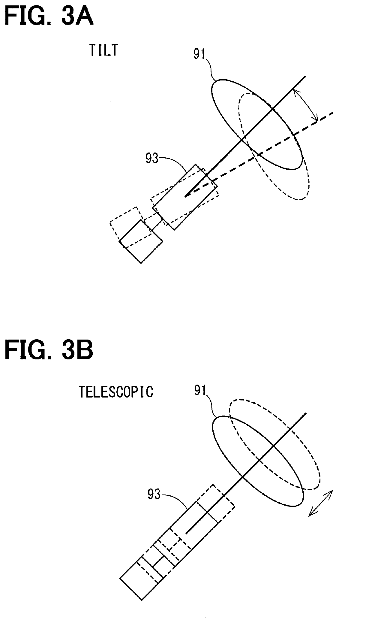
CROSS REFERENCE TO RELATED APPLICATION[0001]The present application is based on and claims the benefit of priority of Japanese Patent Application No. 2018-223293, filed on Nov. 29, 2018, the disclosure of which is incorporated herein by reference.TECHNICAL FIELD[0002]The present disclosure generally relates to a rotating machine controller.BACKGROUND INFORMATION[0003]A rotating machine controller, in the related art, is known to be provided as a device that has one drive circuit to drive a polyphase rotating machine and a direct current (DC) rotating machine.[0004]For example, a motor control device disclosed in the related art drives a three-phase alternating current (AC) motor and two DC motors by one three-phase inverter drive circuit. Specifically, this motor control device is used as a vehicle steering device, and drives a three-phase motor of an electric power steering (EPS) as well as a tilt DC motor and a telescopic DC motor. In such manner, the number of switching elements ...

Claims


Application Information

Patent Timeline
IPC IPC(8): H02P5/60B62D5/04
CPCB62D5/0463H02P5/60H02P25/22H02P29/68H02P21/22H02P27/08B62D1/181B62D5/046
Inventor SUZUKI, TAKASHI
Owner DENSO CORP
Why Eureka
Eureka Blog
Learn More