Charging apparatus for a vehicle and vehicle having a charging apparatus

a charging apparatus and charging device technology, which is applied in the direction of charging stations, electric apparatus casings/cabinets/drawers, transportation and packaging, etc., can solve the problems of affecting the functionality affecting the operation of the charging apparatus, and a large number of control signals, so as to improve the shielding of the filter circuit, compact configuration, and the effect of large space requirements

Active Publication Date: 2020-05-28
DR ING H C F PORSCHE AG
View PDF35 Cites 0 Cited by
  • Summary
  • Abstract
  • Description
  • Claims
  • Application Information

AI Technical Summary

Benefits of technology

[0011]The filter circuit may be in the first shielding chamber. As a result, a particularly compact configuration can be made possible. The filter circuit may be formed separately from the power section, for example as a separate filter board or as part of a printed circuit board that fulfils additional functions.
[0012]The filter circuit may have a shield cover. In the case of a filter circuit arranged in the first shielding chamber together with the power section, shielding of the filter circuit with respect to the power section can be achieved by the shield cover such that the transmission of non-line-related instances of electromagnetic interference between the filter circuit and the power section is reduced.
[0013]The housing has a second shielding chamber formed separately from the first shielding chamber, and the filter circuit may be arranged in the second shielding chamber. This configuration demands a slightly larger space requirement but has the advantage of improved shielding of the filter circuit with respect to the power section. The first and the second shielding chambers may be formed from an electrically conductive material. The first and the second shielding chambers may be arranged adjacent to one another and separated from one another by a common wall that is formed from an electrically conductive material, in particular a metal.

Problems solved by technology

There is a concern that the power section producing electromagnetic interference in the control signals.
Such instances of interference may negatively influence the functionality of the charging apparatus.
Such non-DC-isolated power converters require a comparatively high number of control signals and therefore are particularly susceptible to line-related instances of interference.

Method used


Image

  • Charging apparatus for a vehicle and vehicle having a charging apparatus
  • Charging apparatus for a vehicle and vehicle having a charging apparatus

Examples


Embodiment Construction

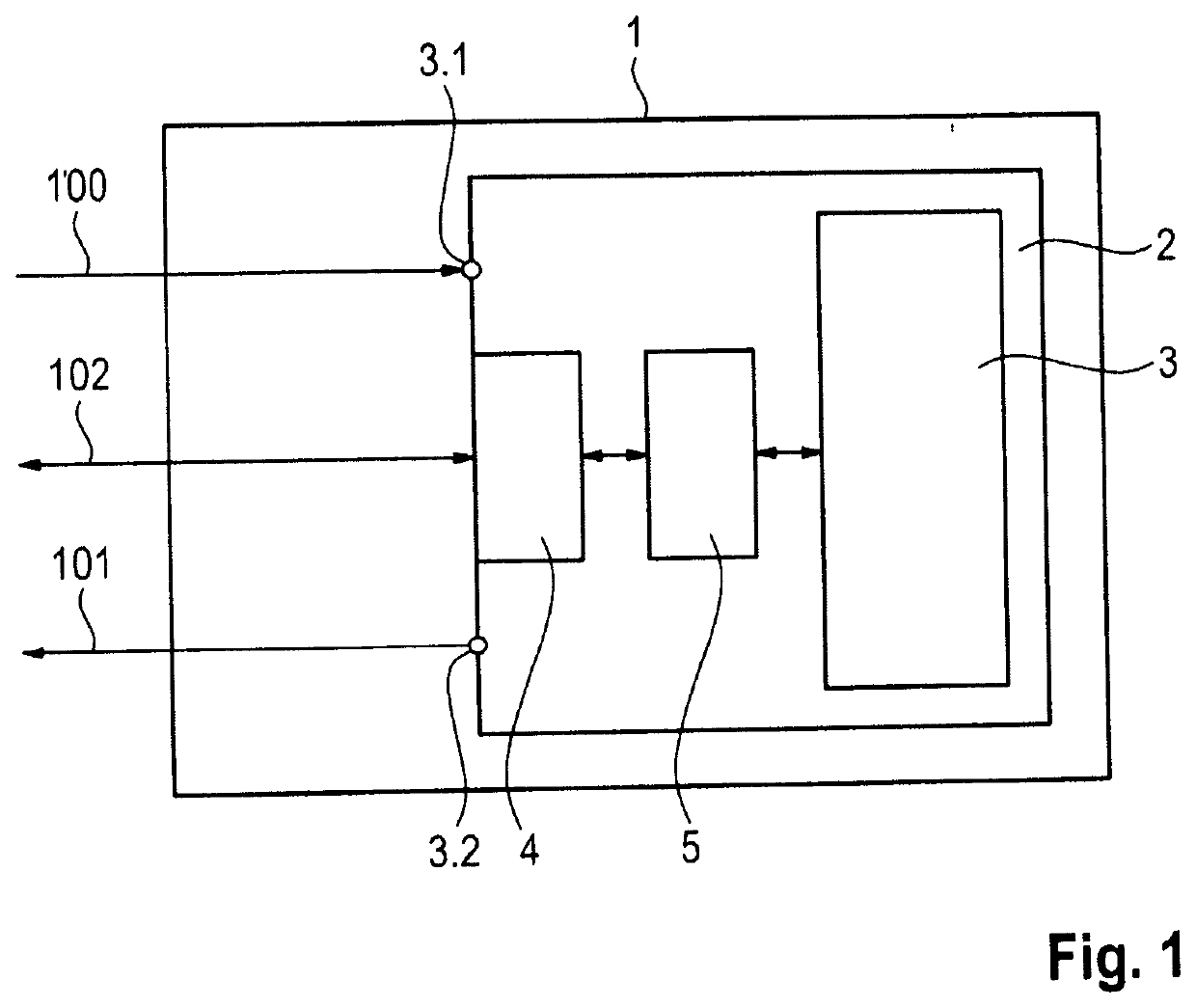
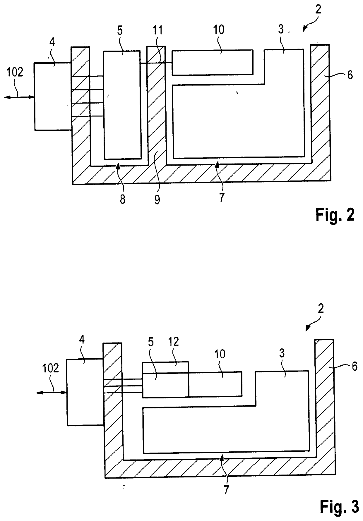
[0021]FIGS. 1-3 schematically illustrate three embodiments of the invention. The elements that are shown schematically in these figures may be implemented in various forms of hardware, software or combinations thereof. Preferably, these elements are implemented in a combination of hardware and software on one or more appropriately programmed general-purpose devices that may include a processor, memory and input / output interfaces. The term “connected” as used herein is defined to mean directly connected to or indirectly connected with or through one or more intermediate components. Such intermediate components may include both hardware and software-based components.

[0022]It will be appreciated by those skilled in the art that the block diagrams of FIGS. 1-3 represent conceptual views of illustrative circuitry and other components embodying the principles of the disclosure. Similarly, it will be appreciated that any functions or methods implied by the figures or cooperation between th...


PUM


Abstract

A charging apparatus (2) for a vehicle (1) has a power section (3) and a control signal interface (4) for connecting control signals (102) to the power section (3). A filter circuit (5), in particular an EMC filter circuit, is arranged between the power section (3) and the control signal interface (4). A vehicle (1) having such a charging apparatus (2) also is provided.

Description

CROSS REFERENCE TO RELATED APPLICATION[0001]This application claims priority under 35 USC 119 to German Patent Appl. No. 10 2018 129 415.8 filed on Nov. 22, 2018, the entire disclosure of which is incorporated herein by reference.BACKGROUNDField of the Invention[0002]The invention relates to a charging apparatus for a vehicle having a power section and a control signal interface for connecting control signals to the power section.Related Art[0003]The power section of a charging apparatus may comprise a power converter that is actuated by control signals. The control signals may be generated by a control unit that is connected to the power section by a control signal interface of the charging apparatus. There is a concern that the power section producing electromagnetic interference in the control signals. Irradiation of electromagnetic interference into the power section also can arise. Such instances of interference may negatively influence the functionality of the charging apparat...

Claims


Application Information

Patent Timeline
Patent Type & Authority Applications(United States)
IPC IPC(8): H02J7/24
CPCH02J7/2434B60L53/00H02M1/44H02J7/14Y02T10/70Y02T10/7072Y02T10/92Y02T90/14H05K1/0216H05K1/14H05K5/0047H05K9/0024H05K9/0037H05K9/0049
Inventor SPESSER, DANIEL
Owner DR ING H C F PORSCHE AG
Why Eureka
Try Eureka