Lens Driving Device With Optical Image Stabilization System

Inactive Publication Date: 2020-05-28
POWERGATE OPTICAL INC
View PDF0 Cites 4 Cited by
  • Summary
  • Abstract
  • Description
  • Claims
  • Application Information

AI Technical Summary

Benefits of technology

The invention is a lens driving device with OIS (optical image stabilization) system. It has a new structure that allows for faster production and reduces production costs. The device is designed to maintain good linear horizontal pushing forces when the horizontal coils are applied with electric currents to move the magnets away from the boundaries of the horizontal coils. These improvements are made through a creative design and configuration of the structure and driving systems of the device.

Problems solved by technology

During batch production, a large area of operation space is required between the lens driving devices 10, thereby increasing the complexity of the process of batch production.
In addition, the operations for applying and curing the damping medium 99 need to be performed at an oblique angle, not only more space and time are required for the processes, but also the productivity is lowered, and the costs are increased.
Thereby, the lens driving devices equipped with OIS of the prior arts are difficult to be manufactured; their manufacturing processes are complex, laborious and costly, and thus are currently deployed in high-end flagship portable electronic products only, not popular in the various applications of the market, and unable to meet the needs of users at all levels for higher camera quality.

Method used


Image

  • Lens Driving Device With Optical Image Stabilization System
  • Lens Driving Device With Optical Image Stabilization System
  • Lens Driving Device With Optical Image Stabilization System

Examples


first embodiment

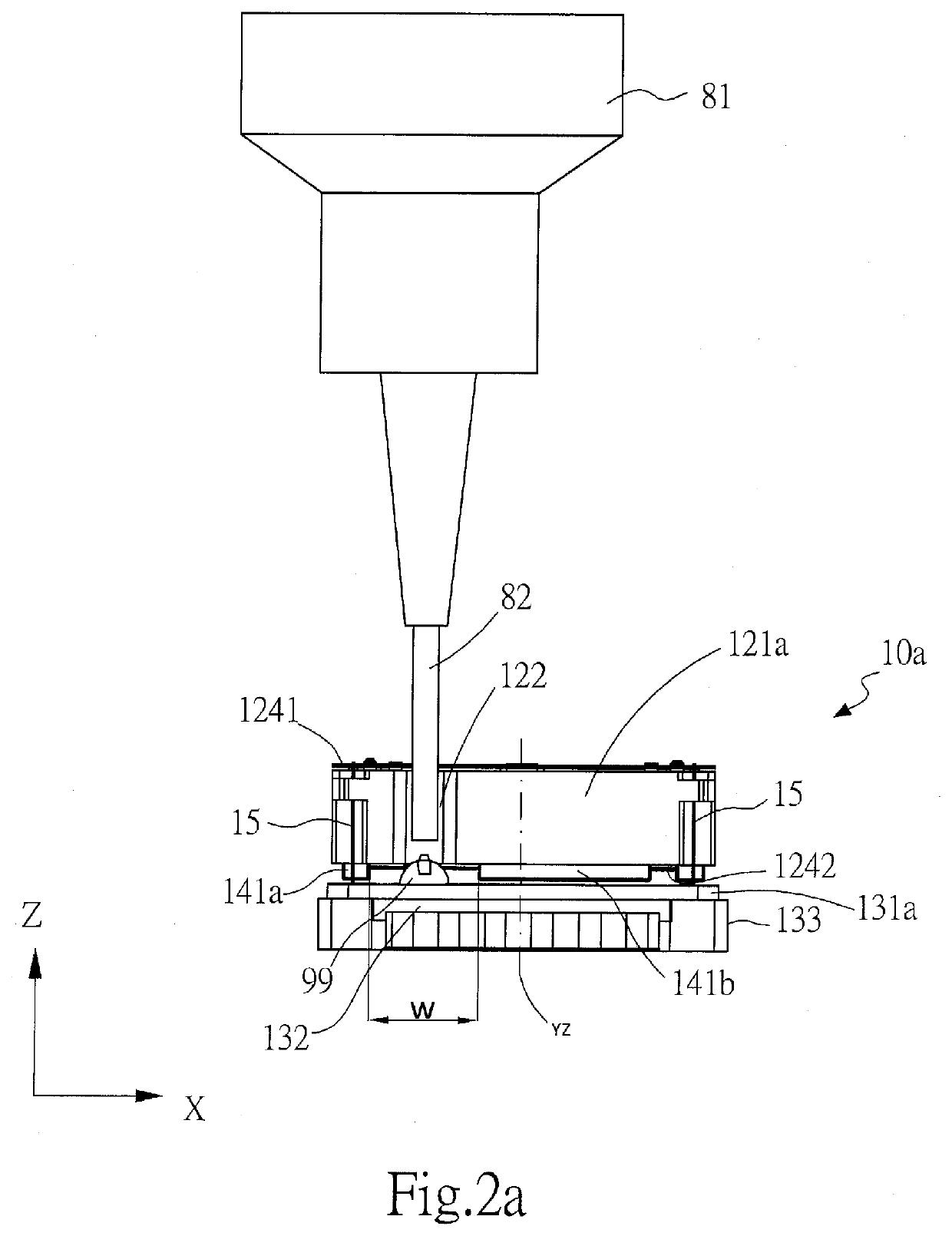
[0043]Please refer to FIGS. 2a-2e, which respectively are a schematic side-view (applying the damping medium), another schematic side-view (curing the damping medium), a schematic perspective view (applying the damping medium), a schematic diagram of the driving system, and a schematic top-view of the configuration of magnets of the lens driving device with OIS system in accordance with the present invention. In order to improve the convenience of the operation of applying the damping medium 99, and to reduce the spacing between the production trays of lens driving devices 10a so as to increase the batch size during the batch production, the lens driving device 10a with OIS system of the invention is specially designed to comprise a plurality of notches 122 furnished on a frame 121a of the movable part. Each notch 122 is extending downward (along Z-axis) from an upper surface of the frame 121a in such a manner that, a bottom of the notch 122 is the location where a damping medium 99...

third embodiment

[0050]The characteristic of lens driving device with OIS system in accordance with the invention as shown in FIG. 3b is that, the magnets 241a, 241b, 2413 mounted in the frame comprise: the distances (M11 and M12) between the second axial plane (YZ) and two ends of the magnet 241b disposed along the first direction (X-axis direction) are different, in which, M11 is shorter than M12. Which means, the center point of the magnet 241b disposed along the first direction is not located at the second axial plane (YZ), and is displaced toward right side by a predetermined distance, so as to leave a gap (that is, the predetermined width W) at the left end of the magnet 241b. The distance between the left end of the magnet 241b and another magnet 241a disposed at left side of the magnet 241b is the predetermined width W, and the notch 222 is formed at the area of width W. Moreover, the magnets 241a, 2413 disposed along the second direction are asymmetrically disposed on the left and right sid...

fifth embodiment

[0052]The characteristic of lens driving device with OIS system in accordance with the invention as shown in FIG. 4b is that, the configuration of asymmetric volumes (V1, V2) of the magnets 2431, 2432 is achieved by changing their thicknesses in the second direction, such that, the thickness in the second direction of the V2 part (right part) of each magnets 2431, 2432 is thicker than the thickness of the V1 part (left part), which results in the volume of the V2 part (right part) to be larger than the V1 part (left part) of each magnets 2431, 2432 disposed along the first direction. By using the larger (thicker) V2 part (right part) of each magnet 2431, 2432 to generate larger magnetic reaction force to balance the autofocusing driving forces, so as to minimize the tilt angle of the lens during the autofocusing operations caused by the asymmetrically configuration of magnets 241a, 2431, 2432.


PUM


Abstract

A lens driving device having an OIS system comprises a movable part equipped with a lens, a fixed part and a driving system for moving the movable part to relative to the fixed part. A plurality of notches are furnished on a frame of the movable part. Each notch extends downward from an upper surface of the frame that, a bottom of the notch is the location where a damping medium is applied. A needle of a damper applying equipment can pass through the notch in a top-to-bottom manner and apply damping medium at the bottom of the notch. In addition, medium curing equipment can apply curing light directly from the top side of the lens driving device for curing the damping medium. Not only the operations for applying and curing the damping medium can be performed in a top-and-down manner and thus decreasing the manufacturing time, but also the placement of the production space between the production trays can be reduced and thus increasing the manufacturing batch.

Description

BACKGROUND OF INVENTION1. Field of the Invention[0001]The invention refers to a lens driving device, especially refers to a VCM lens driving device having AF and OIS system that can be applied with damping medium easily.2. Description of the Prior Art[0002]Lens driving devices equipped with OIS (optical image stabilization) system have the advantages of high reliability and high image resolution, and can provide clear and refined quality of images. Please refer to FIG. 1a which is an exploded perspective view of a basic structure of a typical lens driving devices 10 equipped with OIS system. The lens driving devices 10 generally comprises: a case 11, a movable part 12, a fixed part 13, a driving system 14 and an external circuit 92 having an image sensor 91.[0003]The movable part 12 comprises: a frame 121, a lens support 123 equipped with a lens 1230, and at least one spring plate 1241, 1242 elastically connecting the frame 121 and the lens support 123 (including the lens 1230). The...

Claims


Application Information

Patent Timeline
IPC IPC(8): G02B27/64H04N5/232G03B5/02G02B7/09G03B5/00
CPCG02B27/646G02B7/09G03B5/02H04N5/23287G03B2205/0015G03B5/00H04N23/54H04N23/687G03B3/10G03B2205/0069H04N23/57H04N23/55
Inventor HUANG, YING CHUNCHEN, YU CHIACHUANG, HSIEH JENHO, TE PAO
Owner POWERGATE OPTICAL INC
Why Eureka
Try Eureka