
Melt-Formed Inorganic Fibres

a technology of inorganic fibres and melt-formed fibres, which is applied in the field of aluminium-based inorganic fibres, can solve the problems of low biopersistence, significantly more complex, and high cost of the solubility of the gel process fibr

Pending Publication Date: 2020-05-28
THERMAL CERAMICS UK
View PDF1 Cites 0 Cited by
  • Summary
  • Abstract
  • Description
  • Claims
  • Application Information

AI Technical Summary

Benefits of technology

The present patent provides a needled blanket made of melt-formed inorganic fibers with a specific composition and a shot content. The blanket has a specific surface area, a tensile strength to density ratio, and a fiber arithmetic diameter. The patent also describes an apparatus for producing the fibers and a mass of melt-formed fibers. The technical effects of the invention include improved insulation and reduced shot content in the blanket, as well as improved mechanical properties and a more uniform fiber distribution.

Problems solved by technology

Sol-gel process fibres tend to be more expensive than melt formed fibres as they are significantly more complex to make.
Studies of the toxicology of natural and man-made fibres led to the idea that it was the persistence of fibres in the lung that caused problems.
Whilst several glass systems were known to be soluble in lung fluids, resulting in low biopersistence, there was a problem in that such glass systems were generally not useful for high temperature applications.
In spinning disruption is by one or more high-speed rotors (with or without blowing air around the rotor), such that fibres are flung off the rotors and collected for subsequent processing.
Because of the nature of the molten material, alkaline earth silicate fibres are not blown since extremely low fibre yields and high shot contents are obtained.
US2012 / 247156 indicates that forming alkaline earth silicate fibres with over 70% silica is a problem due to an increase in viscosity of the raw material so that fine fibres (<5 μm) are not obtainable, and that using a high speed rotor, with a stable supply of molten material, and at a temperature providing a defined viscosity can provide fine fibres having a low shot content.
Although methods for reducing shot from bulk fibre are known, and are used in particular to provide fibres for forming vacuum formed products from such fibres, these methods result in severe shortening of the remaining fibre.
Since the tensile strength of a blanket is dependent (among other things) on the length of the fibres, blankets made from deshotted fibres are not commercially available in blanket form, or acceptable for such use, as they show low tensile strength, and in addition the further processing steps of deshotting add to cost.

Method used

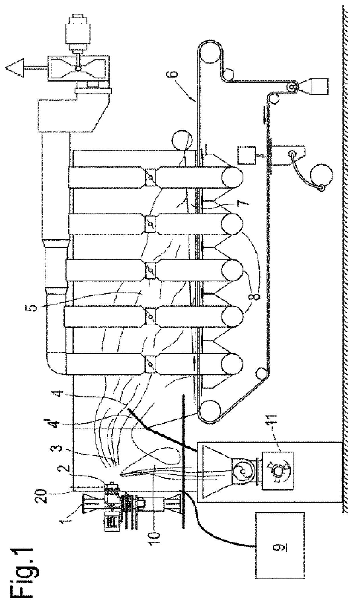
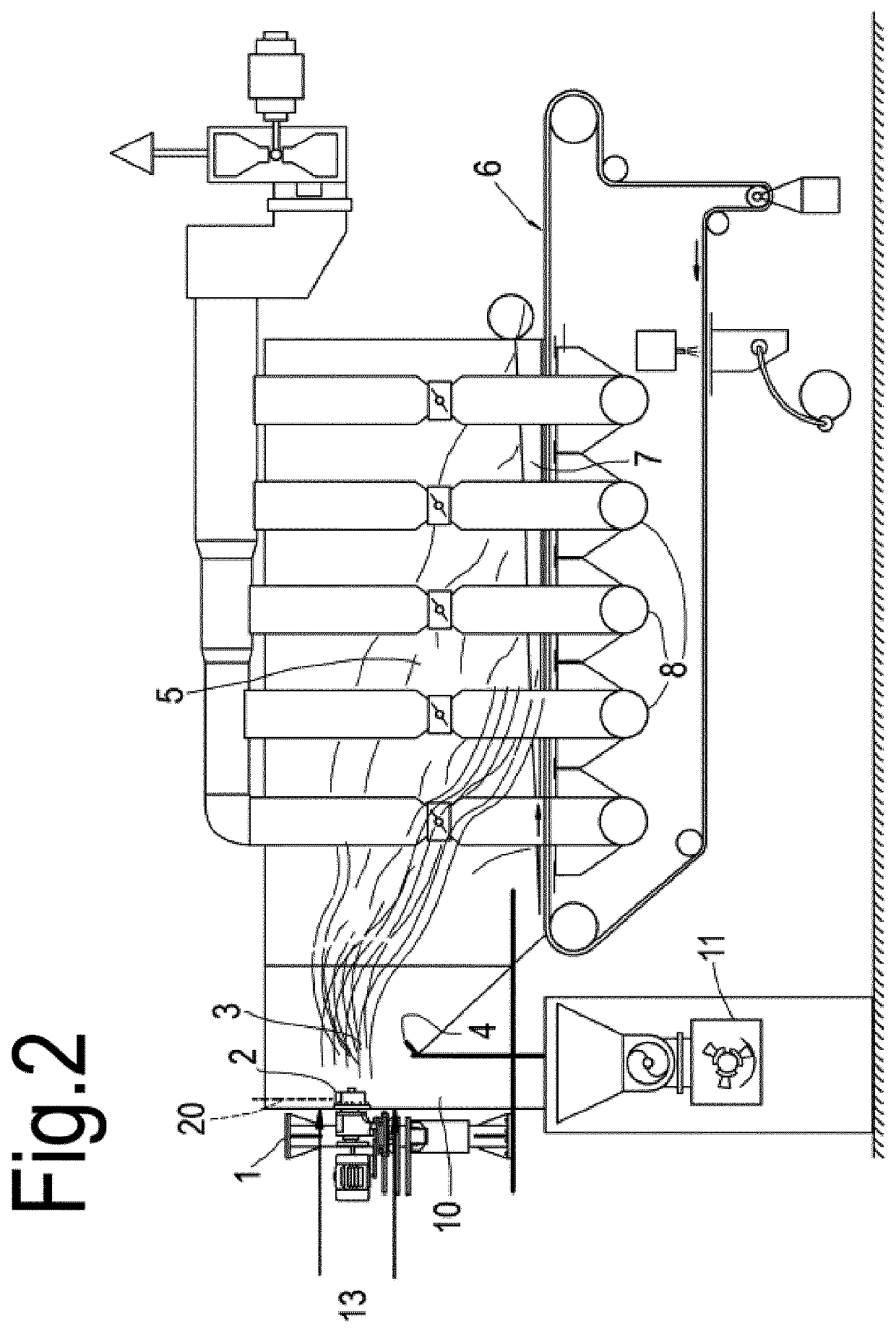
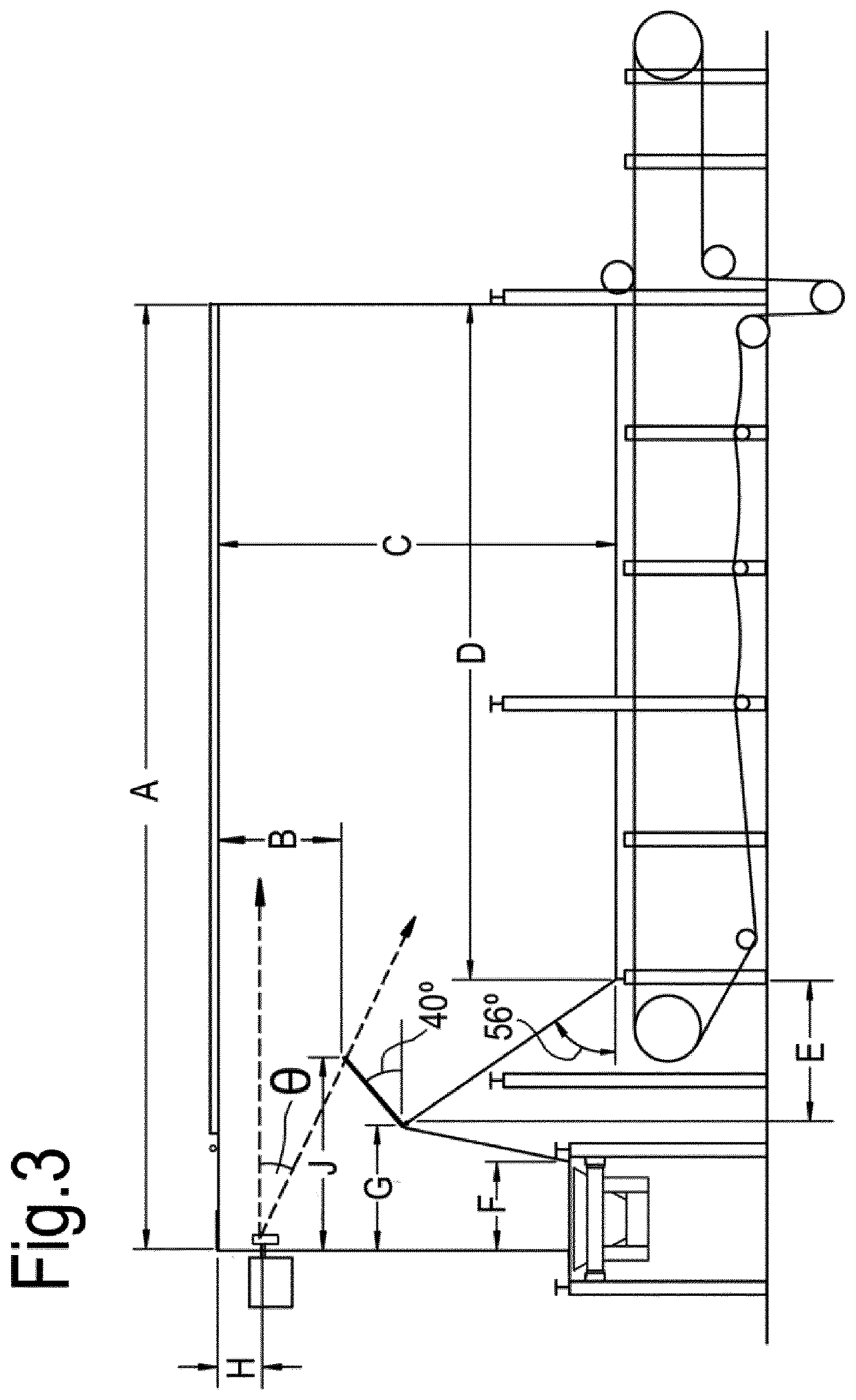

Image

  • Melt-Formed Inorganic Fibres
  • Melt-Formed Inorganic Fibres
  • Melt-Formed Inorganic Fibres

Examples


example 3

[0147]An aluminosilicate fibre was trialled on spinning apparatus as shown in FIG. 2 using pairs of 20 cm (8″) rotors, and the rotor speed increased stepwise from 9000 / 9500 rpm (one rotor at 9000, the other at 9500 rpm) through to both rotors running at 15,000 RPM. Fibre diameter and shot content were measured and the results and fibre composition are set out in FIG. 10.

[0148]With increasing rotor speed both fibre diameter and shot content decreased to provide, at higher speeds, fibres having fibre diameters similar to blown RCF, but shot content similar to or significantly less than spun RCF.

[0149]In light of the results of Example 3 the applicants have compared:[0150]aluminosilicate materials made with the presently claimed apparatus using the rotor configuration of Example 3 and high rotor speeds (both rotors at 14,500 rpm); with, materials made using the presently claimed apparatus using lower rotor speeds[0151]commercially available materials.

example 4

[0152]A “standard” spun refractory ceramic fibre has a typical composition in weight percent:[0153]Alumina 46-48%[0154]Silica 52-54%

and is exemplified by Cerablanket™ (a trademark of Morgan Advanced Materials plc). Such a material has a shot content >45 μm of about 50%.

[0155]A material of the same composition made using the high rotor speeds (both rotors at 14,500 rpm) has a shot content >45 μm of 43-46%.

[0156]Comparative results for thermal conductivity for a 128 kg / m3 blanket measured by ASTM-C201 expressed in W / mK are shown in Table 7.

TABLE 7Thermal Conductivity (W / m · K)TemperatureExampleMorgan Cerablanket ™%(° C.)4-14500 rpmRCF (data sheet)difference2000.060.06 0%4000.080.120%6000.120.1520%8000.170.215%10000.230.2715%

example 5

[0157]Blown fibres tend to be finer than spun fibres, and to hence provide lower thermal conductivity. However blown fibres tend to be shorter than spun fibres and blankets are difficult to make from blown fibres. Blown fibres also tend to have more shot than spun fibres. Typically blown RCF has a shot content >45 μm of above 50%, and above a spun fibre of like composition.

[0158]High alumina (HA) RCF fibre is known for meeting higher temperature applications than standard RCF fibre and is normally blown, as it has proven difficult in the past to spin or make into blanket.

[0159]HA fibres have typical compositions in weight percent:

Alumina50-53%Silica47-50%

[0160]Comparative results for thermal conductivity for a 128 kg / m3 blanket measured by ASTM-C201 expressed in W / mK are shown in Table 8, which compares:[0161]A. a spun HA fibre with composition based on

Alumina50-52%Silica48-50%[0162]made using the high rotor speeds (both rotors at 14,500 rpm) having a shot content >45 μm of 43-46%.[...


PUM

PropertyMeasurementUnit
arithmetic mean diameteraaaaaaaaaa
timeaaaaaaaaaa

Abstract

A needled blanket is provided comprising melt-formed inorganic fibres having an overall composition in weight percent SiO2: 47 to 65%; AI2O3: 35 to 53%; the blanket having • a shot content, of shot >45 μm, of less than 51 wt %, • a specific surface area [BET)>0.25 m2·g−1. also disclosed are fibres for producing such blankets, and self-supporting products made from such fibres.

Description

FIELD OF THE INVENTION[0001]This invention relates to aluminosilicate fibres, blankets made from such fibres, and other products made from such fibres.BACKGROUNDInorganic Fibres[0002]Inorganic fibrous materials are well known for their use as thermal and / or acoustic insulating materials and are also known for their use as strengthening constituents in composite materials such as, for example, fibre reinforced cements, fibre reinforced plastics, and as a component of metal matrix composites. Such fibres may be used in support structures for catalyst bodies in pollution control devices such as automotive exhaust system catalytic converters and diesel particulate filters and may be used in the catalyst bodies themselves. Such fibres may be used as a constituent of friction materials [e.g. for automotive brakes].[0003]Inorganic fibres for use in insulation are well known. A convenient means of providing insulation from inorganic fibres is as blankets comprising said fibres. Since these ...

Claims


Application Information

Patent Timeline
Patent Type & Authority Applications(United States)
IPC IPC(8): D04H1/4218D04H1/46
CPCD10B2101/06D04H1/4218D04H1/46C03B37/055C04B35/62245C04B35/653D04H1/4226C04B2235/5264C04B2235/96C03C13/00C03C3/083
Inventor JUBB, GARYHANKINSON, MICHAELFREEMAN, CRAIG
Owner THERMAL CERAMICS UK
Learn More