
Camera module, electronic device having same and method for manufacturing camera module

Pending Publication Date: 2020-05-21
NINGBO SUNNY OPOTECH CO LTD
View PDF6 Cites 1 Cited by
  • Summary
  • Abstract
  • Description
  • Claims
  • Application Information

AI Technical Summary

Benefits of technology

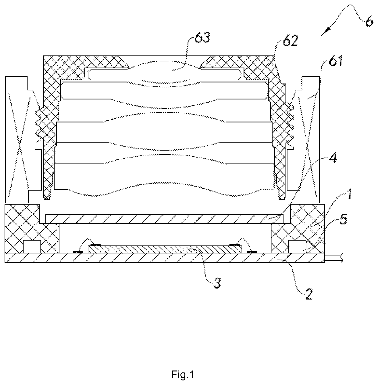
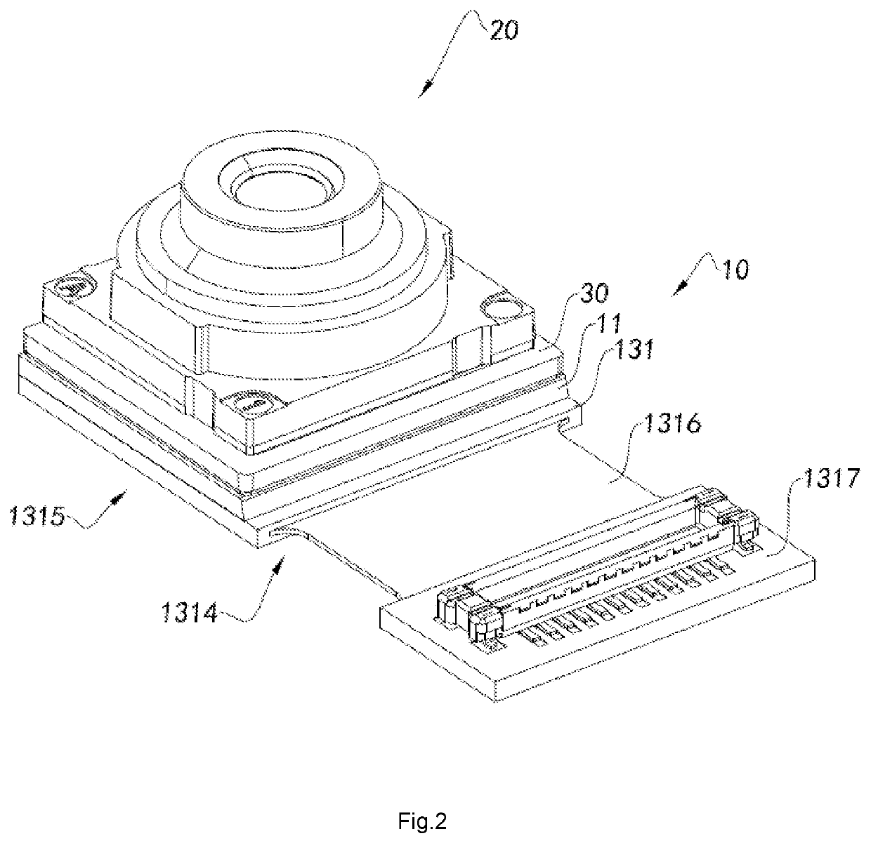
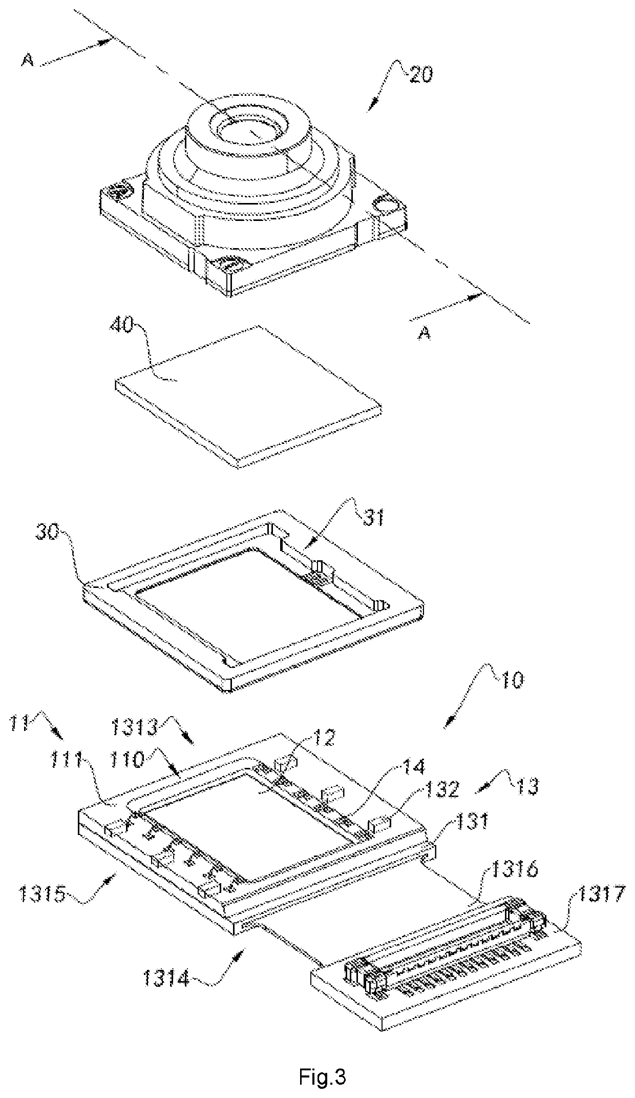
The present disclosure provides a camera module and an electronic device with the same. The camera module has an optical lens directly assembled on the molded base without an additional fixed lens barrel, which reduces space occupied by the barrel and further reduces the size of the camera module. The camera module has a more compact and smaller structure due to the integrally molded base on the circuit board and photosensitive element. There is no need to reserve a safe space for the electronic components, which results in a reduction of the length and width dimensions of the circuit board, improves space utilization of the electronic components, and enhances the intensity of the electronic components relative to the circuit board.

Problems solved by technology

However, those skilled in the art should know that a high imaging quality and high performance camera module means a larger number of camera module components and a larger component size, which will inevitably cause the camera module after being assembled to have a large body size and not to meet the development trend of the current electronic devices.
However, the screen of smart devices cannot be expanded at will, and an oversized mobile phone screen will increase the overall size of the mobile phone, which will in turn affect carrying and one-handed operation.
Due to the limitation of the existing camera module's COB packaging process, the overall size of the finally produced camera module is difficult to meet the requirements.

Method used


Image

  • Camera module, electronic device having same and method for manufacturing camera module
  • Camera module, electronic device having same and method for manufacturing camera module
  • Camera module, electronic device having same and method for manufacturing camera module

Examples


Embodiment Construction

[0061]The following description is presented to disclose the present disclosure to enable those skilled in the art to practice the present disclosure. Preferred embodiments in the following description are by way of example only, and other obvious modifications are conceivable to those skilled in the art. The basic principles of the present disclosure as defined in the following description may be applied to other implementations, modifications, improvements, equivalents, and other technical solutions without departing from the spirit and scope of the present disclosure.

[0062]It should be understood by those skilled in the art that in the disclosure of the present disclosure, the orientation or positional relationship indicated by the terms “longitudinal”, “transverse”, “upper”, “lower”, “front”, “back”, “left”, “right”, “vertical”, “horizontal”, “top”, “bottom”, “inside”, “outside”, etc. is based on the orientation or positional relationship shown in the figures, which is merely fo...


PUM


Abstract

A camera module and an electronic device having the same, and a method for manufacturing the camera module, wherein the fixed-focus camera module comprises a circuit board; a photosensitive element, which is conductively connected to the circuit board; a molded base, wherein the molded base is integrally molded on the circuit board and the photosensitive element, and the molded base forms a light window, so as to provide a light passage for the photosensitive chip through the light window; and an optical lens, wherein the optical lens is supported on the molded base and corresponds to the light window formed by the molded base, wherein the circuit board comprises a circuit board substrate and at least one electronic component, wherein the at least one electronic component is electrically connected to the circuit board substrate, wherein the circuit board substrate has a blank side, and wherein the blank side of the circuit board substrate is free of the at least one electronic component.

Description

TECHNICAL FIELD[0001]The present disclosure relates to the field of camera modules, and further relates to a camera module, an electronic device having the same and a method for manufacturing the camera module.TECHNICAL BACKGROUND[0002]With the development of science and technology, electronic products and smart devices have developed by leaps and bounds. The mainstream trend is that while electronic devices are increasingly thin and light, their comprehensive performance and user experience requirements are constantly updated and iterated. As one of indispensable components of the electronic products and smart devices, camera modules are also increasingly required to be multifunctional, thin, and miniaturized to meet the development trend of the electronic devices and smart products.[0003]More specifically, the current electronic products, such as smart phones, are becoming thinner. In this technology trend, the height dimension (thickness dimension) of the camera module is compres...

Claims


Application Information

Patent Timeline
IPC IPC(8): H04N5/225G02B7/02B29D11/00
CPCB29D11/0048B29L2011/0016H04N5/2254H04N5/2257G02B7/021H05K3/0014H04N23/50H04N23/57H04N23/55H01L27/14618H01L27/14625H04N23/54
Inventor WANG, MINGZHUZHAO, BOJIEMEI, ZHEWENGUO, NANYAO, LIFENGCHEN, ZHENYU
Owner NINGBO SUNNY OPOTECH CO LTD
Learn More