
Work implement assembly using a center adapter cover

Active Publication Date: 2020-05-21
CATERPILLAR INC
View PDF0 Cites 11 Cited by
  • Summary
  • Abstract
  • Description
  • Claims
  • Application Information

AI Technical Summary

Benefits of technology

The present disclosure describes an adapter cover for a work implement assembly that includes a shell body with a thru-hole for attaching a tool. The adapter cover also has a front face portion, top and bottom legs, and a center adapter cover for attachment to a base edge. The center adapter cover includes a body with a nose portion for attaching a tool, first and second legs with an aperture for receiving a mounting mechanism, a slot for assembly onto the work implement, and recesses for receiving the top and bottom legs of the adapter cover. The technical effect of this design is a versatile and secure attachment of a tool to a work implement assembly.

Problems solved by technology

However, current adapters do not always meet customer requirements for longevity or durability.

Method used


Image

  • Work implement assembly using a center adapter cover
  • Work implement assembly using a center adapter cover
  • Work implement assembly using a center adapter cover

Examples


Embodiment Construction

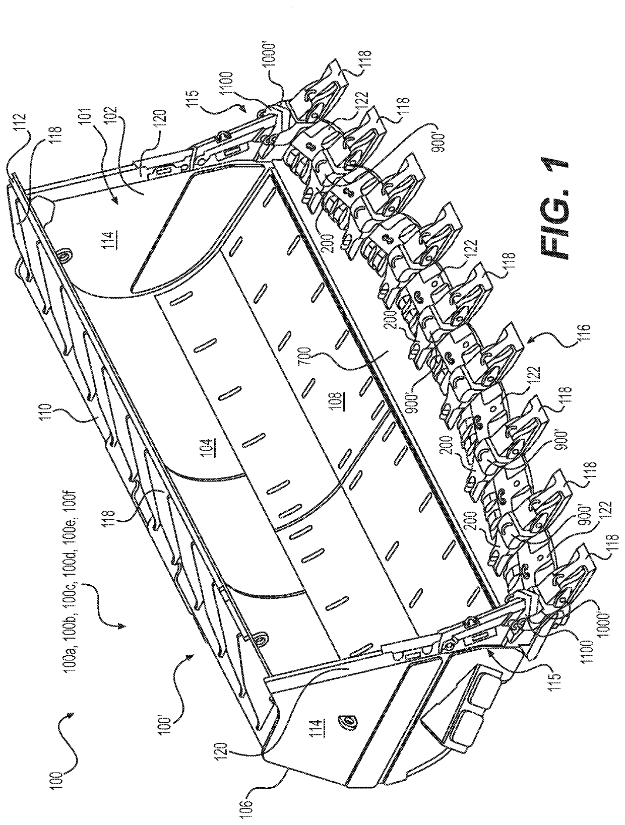
[0043]Reference will now be made in detail to embodiments of the disclosure, examples of which are illustrated in the accompanying drawings. Wherever possible, the same reference numbers will be used throughout the drawings to refer to the same or like parts. In some cases, a reference number will be indicated in this specification and the drawings will show the reference number followed by a letter for example, 100a, 100b or a prime indicator such as 100′, 100″ etc. It is to be understood that the use of letters or primes immediately after a reference number indicates that these features are similarly shaped and have similar function such as is often the case when geometry is mirrored about a plane of symmetry. For ease of explanation in this specification, letters or primes will often not be included herein but may be shown in the drawings to indicate duplications of features discussed within this written specification.

[0044]A work implement assembly using center adapters, corner ...


PUM


Abstract

An adapter cover includes a shell body including an exterior surface, an interior surface, and defining a vertical direction, a horizontal direction, and a vertical plane, a front face portion defining a thru-hole, a top leg extending horizontally from the front face portion and defining an adapter key receiving recess on the interior surface and a top leg side portion defining a concave arcuate portion extending rearward from the front face portion, a convex arcuate portion extending horizontally from the concave arcuate portion, terminating in a vertical rear surface, and a bottom leg extending horizontally from the front face portion.

Description

CROSS-REFERENCE TO RELATED APPLICATION[0001]This non-provisional patent application claims the benefit of U.S. Provisional Patent Application No. 62 / 768,403, filed on Nov. 16, 2018, entitled “Advansys Mechanically Attached Adaptor”, the contents of which is hereby incorporated by reference in its entirety.TECHNICAL FIELD[0002]The present disclosure relates to work implement assemblies such as bucket assemblies used by earth moving, mining, construction equipment and the like. More specifically, the present disclosure relates to such assemblies that employ a notched base edge and tool adapters mating with the base edge.BACKGROUND[0003]Machines such as wheel loaders, excavators, and the like employ work implement assemblies including bucket assemblies, rakes, shears, etc. that have teeth or tips attached to them to help perform work on a material such as dirt, rock, sand, etc. For example, teeth or tips may be attached to a bucket assembly to help the bucket assembly to penetrate the ...

Claims


Application Information

Patent Timeline
IPC IPC(8): E02F9/28
CPCE02F9/2825E02F9/2883E02F9/2808E02F9/2858E02F9/285E02F3/40E02F9/2891F16B1/00F16F2230/02
Inventor SINN, ERIC T.SERRURIER, DOUGLAS C.YOEU, RAMMAGY
Owner CATERPILLAR INC
Learn More