
Electrical screening device for structures near high voltage parts of electrostatic precipitators

Active Publication Date: 2013-10-31
ANDRITZ AB
View PDF18 Cites 9 Cited by
  • Summary
  • Abstract
  • Description
  • Claims
  • Application Information

AI Technical Summary

Benefits of technology

The patent text describes an electrical screening device that helps prevent fire outbreaks in electrical equipment. The device has a rounded or arched shape, which eliminates sharp edges that could lead to spark-over. It can be easily attached to existing or new support structures using a bracket. The technical effects of this device are improved safety and reliability in electrical equipment, as well as increased flexibility in installation options.

Problems solved by technology

However, due to sparking between structural parts the power input to the electrostatic precipitator has become low.
Such cut-outs have been found insufficient in recent high voltage testing and spark-over has occurred despite the cut-outs.

Method used


Image

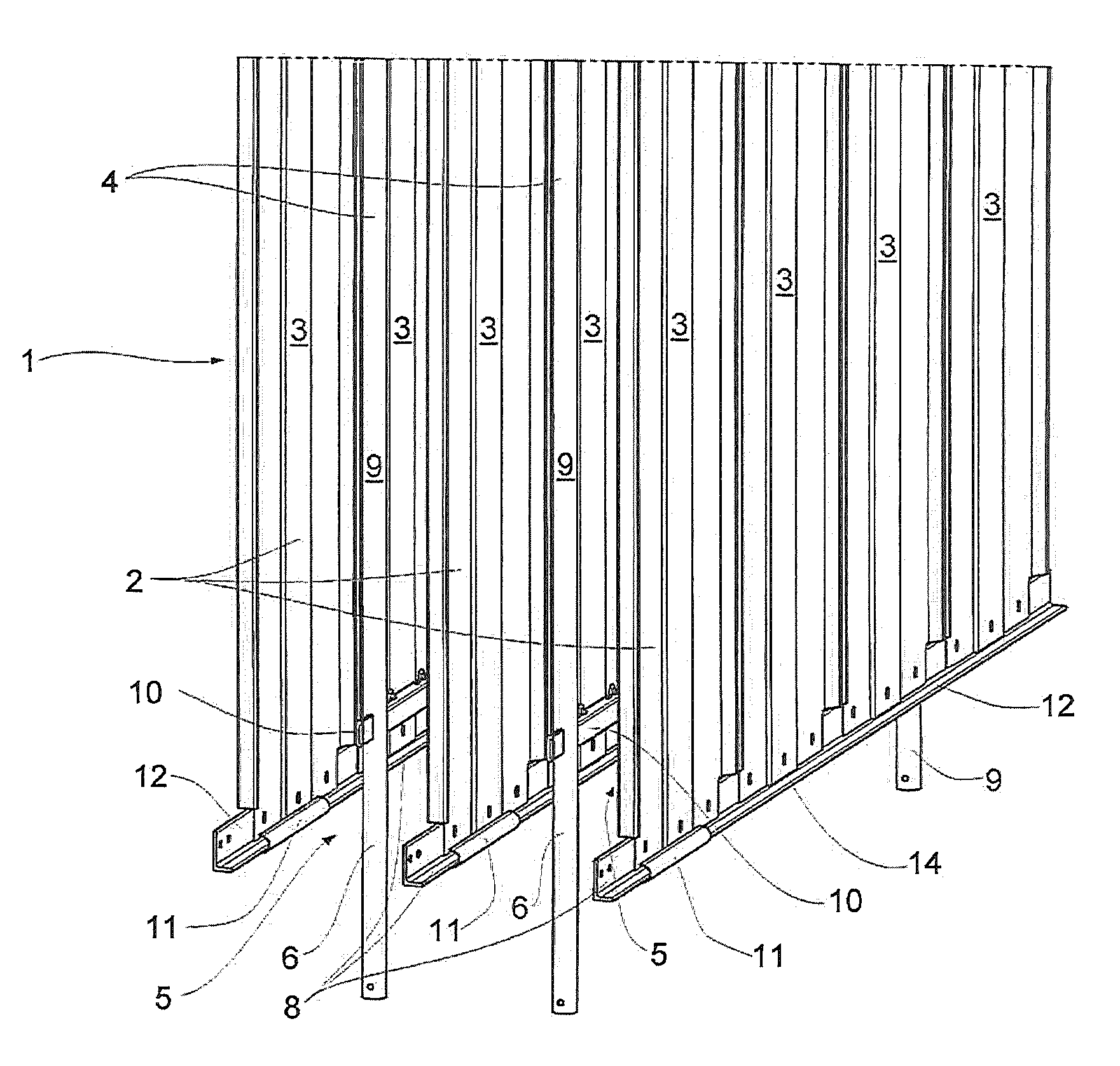
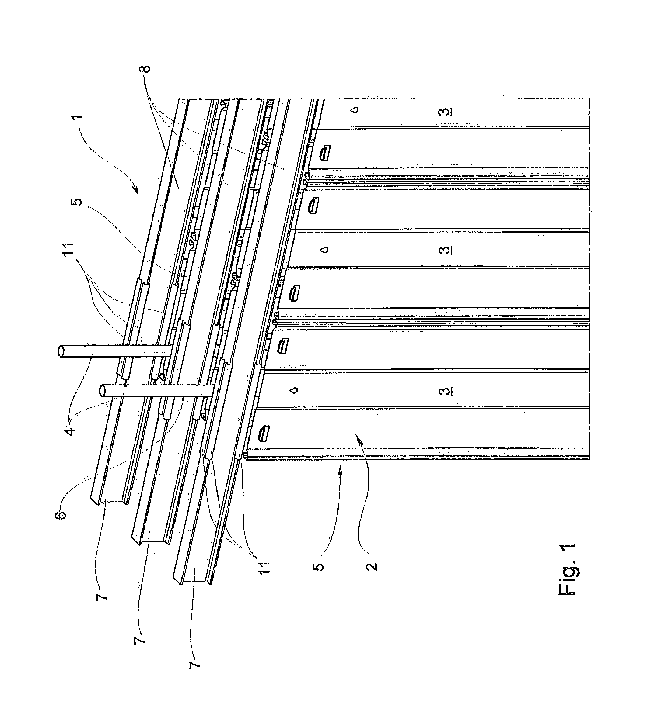
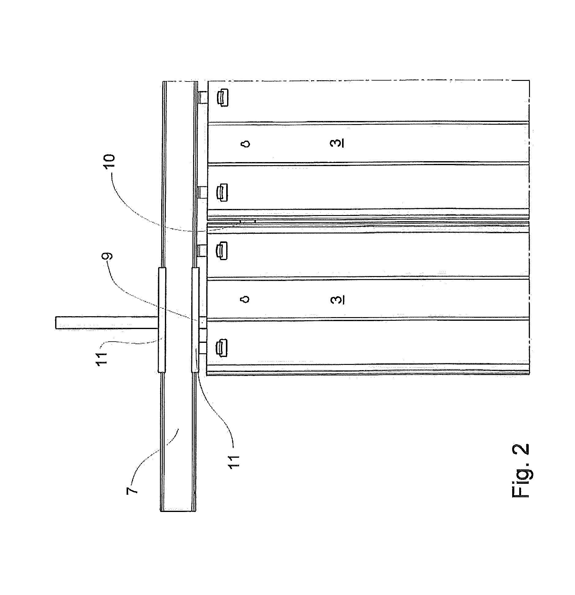
  • Electrical screening device for structures near high voltage parts of electrostatic precipitators
  • Electrical screening device for structures near high voltage parts of electrostatic precipitators
  • Electrical screening device for structures near high voltage parts of electrostatic precipitators

Examples


Embodiment Construction

[0020]An electrostatic precipitator having generally a housing (not shown) with an inlet (not shown), an outlet (not shown) and a precipitation chamber disposed therebetween. The particulate laden flue gas to be cleaned passes through the housing (not shown) of the precipitator passing from the gas inlet through the precipitation chamber and to the gas outlet as a clean, relatively particulate free gas.

[0021]Referring now to the drawings, and most particularly to FIGS. 1 and 4, the basic configuration of an electrostatic precipitator 1 is depicted therein, and is typically referred to as a rigid frame-type electrostatic precipitator. A grounded supporting structure 8 including upper support beams 7 and lower support beams 12 carries a plurality of substantially rectangular collecting electrode plates3, forming collectively a collecting electrode plate assembly 2, are disposed in substantially parallel, spaced relationship in vertical planes within the electrostatic precipitator 1. T...


PUM


Abstract

An electrostatic precipitator (1) having a collecting electrode plate assembly (2), including at least two electrode plates (3) disposed substantially in a parallel to each other in the vertical plane within the electrostatic precipitator (1), forming a space (5) between the collecting electrode plates (3), and a discharge electrode assembly (4) interposed in said spaces (5), wherein the electrode assembly (4) passing at least a supporting structure (8) of the collecting electrode plate assembly (2). The supporting structure (8) is provided with an electrical screening device (11) at least in the area of the supporting structure (8) facing said electrode assembly (4).

Description

FIELD OF THE INVENTION[0001]This invention relates to an electrostatic precipitator having a collecting electrode plate assembly, including at least two electrode plates disposed substantially in a parallel to each other in the vertical plane within the electrostatic precipitator, forming a space between the collecting electrode plates, and a discharge electrode assembly interposed in said spaces, wherein the electrode assembly passing at least a supporting structure of the collecting electrode plate assembly.BACKGROUND ART[0002]Electrostatic precipitators are well known in the prior art and as an example U.S. Pat. No. 4,725,289 disclose a rigid-frame type electrostatic precipitator. In the operation of an electrostatic precipitator, a gas laden with entrained particulate material is passed through an electrostatic field and corona discharge established about a discharge electrode disposed between two grounded collecting electrodes. The particles in the gas become electrically charg...

Claims


Application Information

Patent Timeline
IPC IPC(8): B03C3/47
CPCB03C3/47B03C3/70
Inventor JOHANSSON, PER BENGT DANIELBACK, ANDREAS OLOF
Owner ANDRITZ AB
Learn More