Cooling bed system

a bed and cooling technology, applied in the field of cooling bed systems, can solve the problems of brain damage as well as tissue damage, and achieve the effects of convenient cleaning, effective and safe cooling of patients, and controlled cooling rate of patients

Inactive Publication Date: 2020-05-21
MAZ MEDICAL LLC
View PDF0 Cites 0 Cited by
  • Summary
  • Abstract
  • Description
  • Claims
  • Application Information

AI Technical Summary

Benefits of technology

The patent describes a cooling system for patients that uses air moving devices to efficiently cool the patient. The system has an upper and lower cooling portion with filters to remove contaminants from the air. The air temperature control device adjusts the temperature of the air. The system also has liquid misters to dispense a mist of liquid onto the patient, and a liquid temperature controller to adjust the temperature of the liquid. The system provides a positive pressure within the enclosure area and is powered by batteries or a portable power generating device. The frame of the system is made of stainless steel and may have adjustable feet and wheels for easy access and transportation. The technical effects of the cooling system include efficient cooling, control over air temperature, and prevention of infection and contamination.

Problems solved by technology

Cooling too rapidly may lead to shock and cooling too slowly may lead to tissue damage as well as brain damage.

Method used


Image

  • Cooling bed system
  • Cooling bed system
  • Cooling bed system

Examples


Embodiment Construction

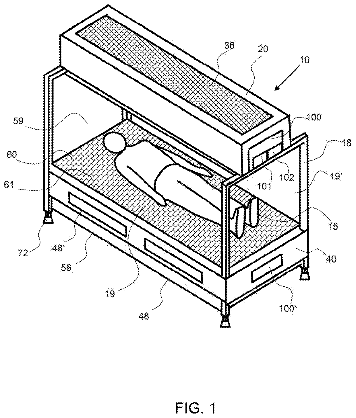
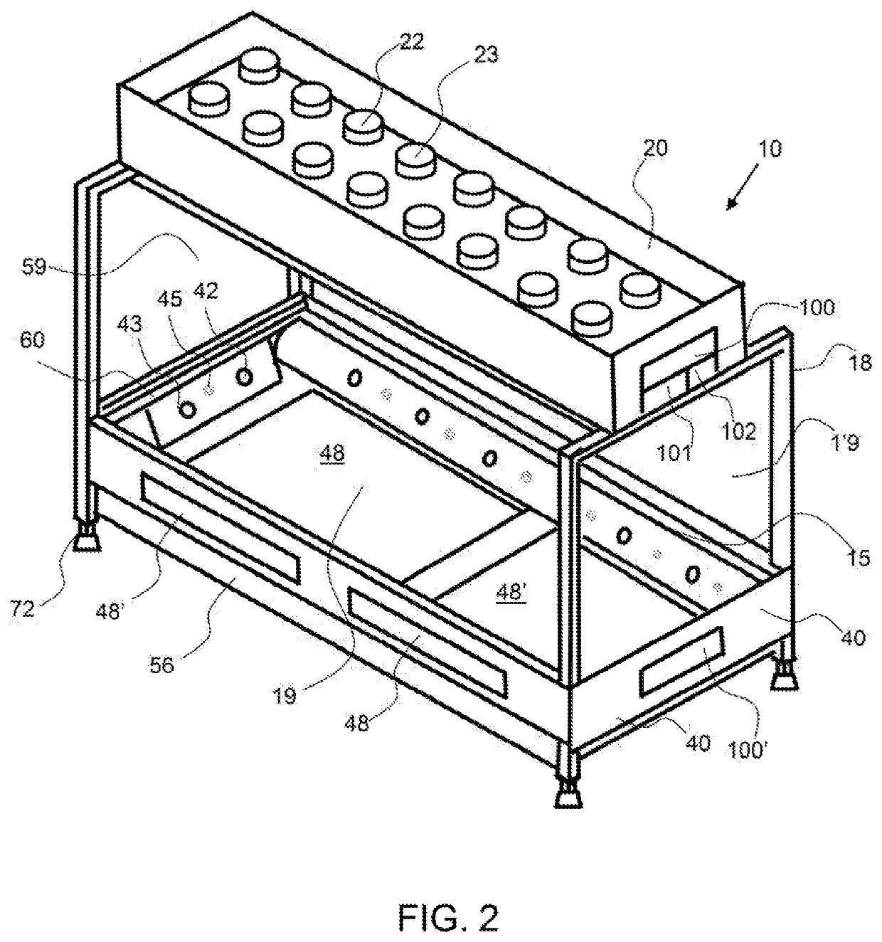
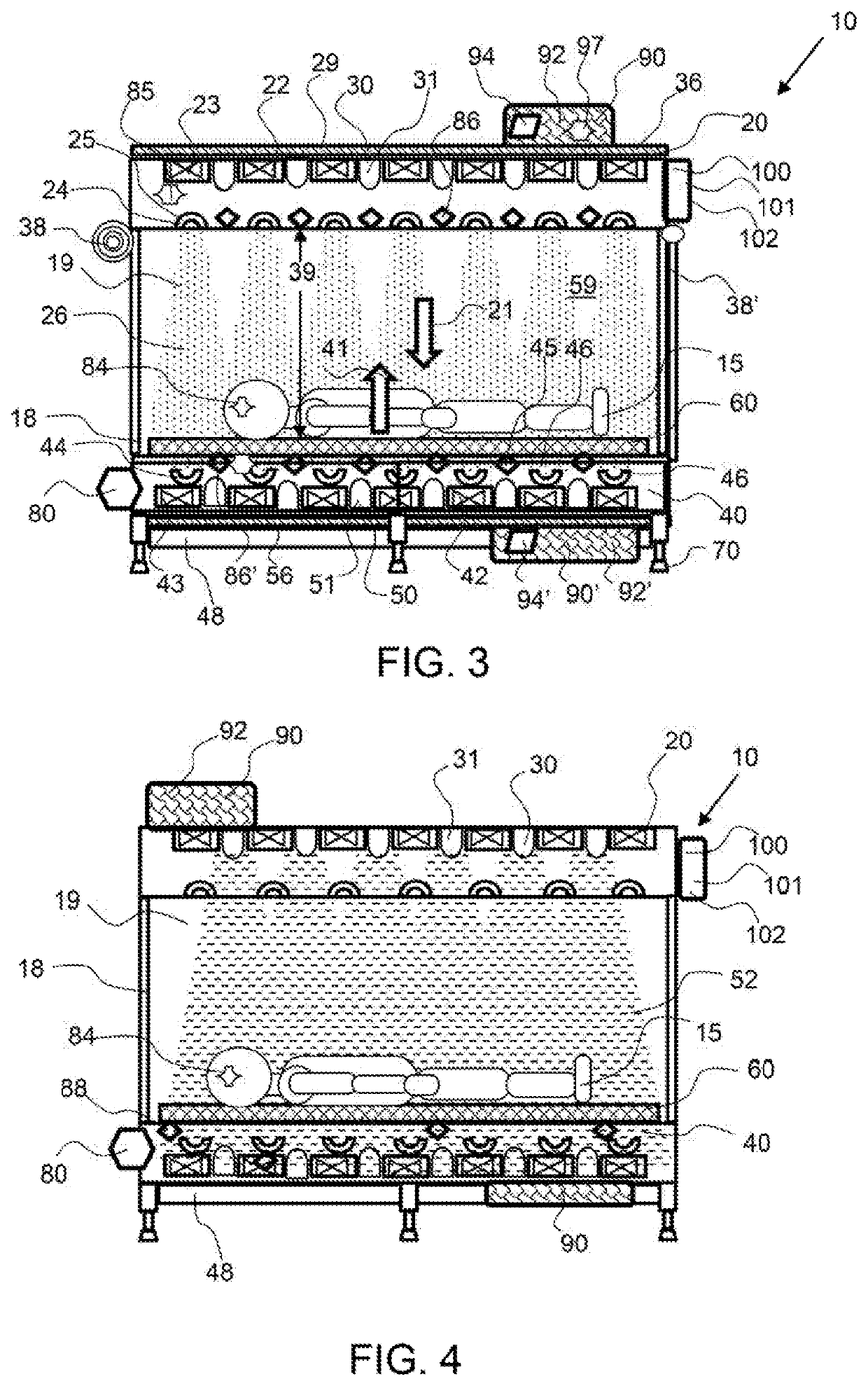
[0023]Corresponding reference characters indicate corresponding parts throughout the several views of the figures. The figures represent an illustration of some of the embodiments of the present invention and are not to be construed as limiting the scope of the invention in any manner. Further, the figures are not necessarily to scale, some features may be exaggerated to show details of particular components. Therefore, specific structural and functional details disclosed herein are not to be interpreted as limiting, but merely as a representative basis for teaching one skilled in the art to variously employ the present invention.

[0024]As used herein, the terms “comprises,”“comprising,”“includes,”“including,”“has,”“having” or any other variation thereof, are intended to cover a non-exclusive inclusion. For example, a process, method, article, or apparatus that comprises a list of elements is not necessarily limited to only those elements but may include other elements not expressly ...


PUM


Abstract

A cooling bed system is configured to provide a cooling airflow around a patient suffering from heat exhaustion, heat stroke and or burns. A cooling bed system produces an airflow over a patient and preferably an airflow from both above and below the patient to more effectively and quickly cool the patient A cooling bed system may also include a liquid dispenser that creates mist that is carried by the airflow to further cool the patient. A patient may be supported by a platform having a plurality of openings to allow airflow and mist to pass therethrough. A controller controls the airflow rate and / or temperature of the air, and may also control the liquid dispensing rate and / or temperature of the liquid as a function of an input from a temperature sensor to effectively and safely cool the patient.

Description

CROSS REFERENCE TO RELATED APPLICATIONS[0001]This application is a continuation of U.S. patent application Ser. No. 15 / 683,754 filed on Aug. 22, 2018 and currently pending, which claims the benefit of U.S. provisional patent application No. 621378,076, entitled Cooling Bed System and filed on Aug. 22. 2016; the entirety of both applications are hereby incorporated by reference herein.BACKGROUND OF THE INVENTIONField of the Invention[0002]The invention relates to a cooling bed system for patients that are overheated or are suffering from a heat stroke.Background[0003]Heat stroke is a life-threatening condition characterized by a high core body temperature or more than 40° C. and a disturbed level of consciousness. It is a common occurrence for those that engage in physical activities, especially outdoor activity. Athletes, police and, those in the military often are affected by overheating and heat stroke. The degree of tissue damage is dependent on the degree and duration of hyperth...

Claims


Application Information

Patent Timeline
Patent Type & Authority Applications(United States)
IPC IPC(8): A61F7/00A61L9/20A61L2/10
CPCA61F2007/0086A61L2/10A61F2007/0062A61M21/0094A61F7/0085A61F2007/0096A61L9/20A61F2007/0064A61F7/0053A61F2007/0093
Inventor ALZEER, ABDULAZIZ HAMADSMITH, TROY
Owner MAZ MEDICAL LLC
Why Eureka
Try Eureka