Electric wire and stator
a technology of electric wire and stator, which is applied in the direction of insulated conductors, windings, insulation materials, etc., can solve the problems of increasing material costs, manufacturing costs, or the like, and achieves excellent insulation properties, low cost and high performance stators.
- Summary
- Abstract
- Description
- Claims
- Application Information
AI Technical Summary
Benefits of technology
Problems solved by technology
Method used
Image
Examples
first embodiment
(Stator)
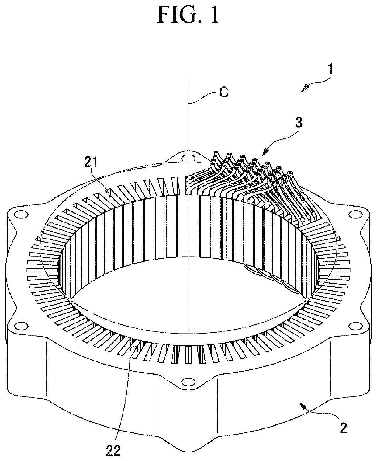
[0030]FIG. 1 is a perspective view of appearance of a stator 1. The stator 1 includes a stator core 2 and a coil 3. Further, in FIG. 1, a part of the coil 3 is omitted for the convenience of description.
[0031]The stator core 2 is formed in an annular shape about an axis C. Teeth 21 are formed on an inner circumferential surface of the stator core 2. The teeth 21 protrude inward from the inner circumferential surface of the stator core 2 in a radial direction. A plurality of teeth 21 are formed in a circumferential direction.
[0032]Slots 22 are formed between the teeth 21, and the coil 3, which will be described below, is inserted into the slots 22. A rotor (not shown) is rotatably disposed about the axis C in the stator core 2.
[0033]In the following description, a direction along the axis C of the stator core 2 may be referred to as an axial direction, a direction perpendicular to the axis C may be referred to as a radial direction, and a direction around the axis C may be re...
second embodiment
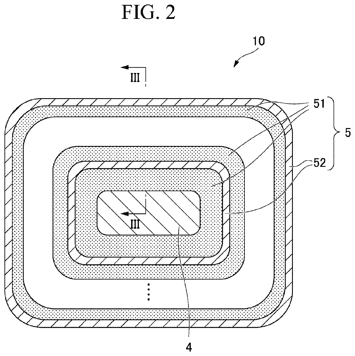
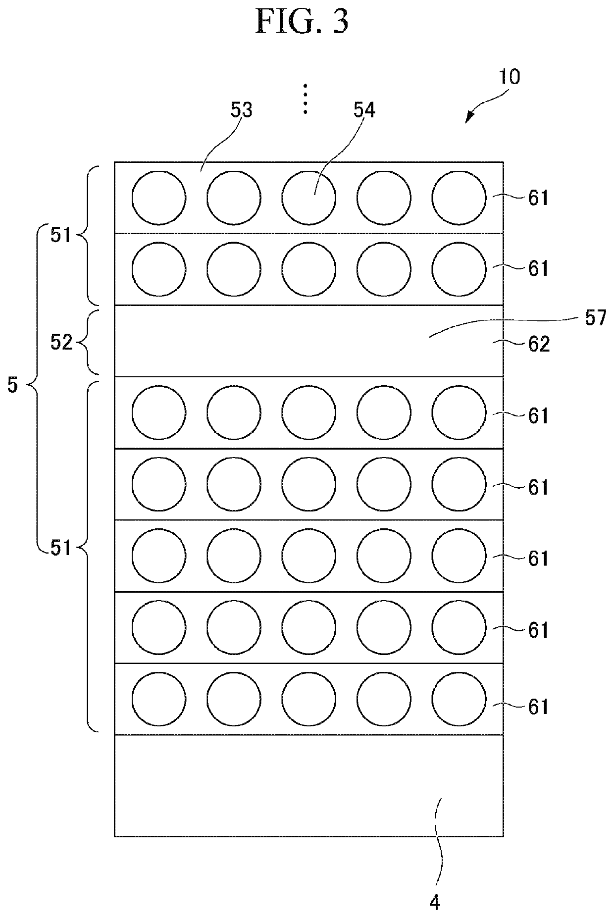
[0064]Next, a second embodiment according to the present invention will be described. FIG. 6 is a cross-sectional view of the electric wire 10 according to the second embodiment, taken along line in FIG. 2. The second embodiment is distinguished from the above-mentioned embodiment in that the porous layer 51 has one porous layer forming film 61. In the following description, components the same as those in the above-mentioned first embodiment are designated by the same reference numerals and appropriate description thereof will be omitted.
[0065]In the embodiment, the porous layer 51 has one porous layer forming film 61. The non-porous layer 52 has one non-porous layer forming film 62. The porous layer 51 and the non-porous layer 52 are alternately disposed in the radial direction of the conductor 4. In other words, the porous layer forming film 61 and the non-porous layer forming film 62 are alternately disposed one at a time in the radial direction of the conductor 4.
[0066]Accordin...
PUM
| Property | Measurement | Unit |
|---|---|---|
| thickness | aaaaa | aaaaa |
| size | aaaaa | aaaaa |
| distance | aaaaa | aaaaa |
Abstract
Description
Claims
Application Information
 - R&D
- Intellectual Property
- Life Sciences
- Materials
- Tech Scout
- Unparalleled Data Quality
- Higher Quality Content
- 60% Fewer Hallucinations
Browse by: Latest US Patents, China's latest patents, Technical Efficacy Thesaurus, Application Domain, Technology Topic, Popular Technical Reports.
© 2025 PatSnap. All rights reserved.Legal|Privacy policy|Modern Slavery Act Transparency Statement|Sitemap|About US| Contact US: help@patsnap.com


