Termination assembly

a technology of assembly and umbilical, which is applied in the direction of mechanical equipment, transportation and packaging, brake systems, etc., can solve the problems of difficult connection of the umbilical at each end, particularly the load of the umbilical handling, and the difficulty of manoeuvring the umbilical into position, so as to reduce the cost, reduce the degree of flexibility, and facilitate the transfer of loads

Active Publication Date: 2020-04-09
JDR CABLE SYST
View PDF0 Cites 1 Cited by
  • Summary
  • Abstract
  • Description
  • Claims
  • Application Information

AI Technical Summary

Benefits of technology

The present invention provides an assembly for terminating an umbilical, which helps in welding the tubes to the main bulkhead plate without requiring large tolerances. The assembly includes a bulkhead with concave recesses and ball elements with a spherical body portion and an elongated channel. The ball elements are inserted into the recesses to prevent them from passing through the bulkhead. The spherical body of the ball element helps in accommodating the angle of the umbilical elements, minimizing any re-alignment or bending, which improves load transfer between the plate and tubes. Overall, the assembly helps create a reliable and capable joint for superior axial load transfer.

Problems solved by technology

Such umbilicals may be large and heavy making the connection of the umbilical at each end challenging.
The loading strains associated with the handling of umbilicals are particularly an issue of concern when terminating the lines with a UTA, where the forces are concentrated.
However, the steel tubes are relatively stiff and so manoeuvring them into position can be relatively challenging, particularly if they have to be bent into the desired shape.
If the steel tube axis is not perfectly perpendicular to the bulkhead plate, it is difficult to get them to pass through the holes without flexing them or enlarging the holes to allow a degree of misalignment.
Misalignment of the tube results in poor quality welding between the tubes and the bulkhead plate.
As an umbilical potentially comprises a large number of helically wound umbilical members, it would be extremely difficult and time consuming to attempt to straighten and align the umbilical members.
These misalignments pose two major drawbacks for the welding process.
Firstly, due to the anticipation of tube misalignments, each plate hole has to be machined with a diameter significantly larger than its intended tube counterpart, which leads to an undesired, significant gap around the tube which affects the overall quality and load transfer reliability of the welds formed.
Secondly, misalignments of this nature are not compatible with automatic welding processes such as orbital welding machines.
Should the tube axis fail to be perpendicular to the bulkhead plate, the welding interface will not be circular, and the welding head will not follow the intersection of the tube and the plate leading to an uneven weld of lower reliability and quality.
Attempting to simultaneously align several steel tubes with the bulky bulkhead remains a difficult and demanding task.
Any misalignments, however slight, can result in unbalanced loading transfer and therefore potential weak spots or areas in the welding between the tubes and plate.

Method used


Image

  • Termination assembly
  • Termination assembly
  • Termination assembly

Examples


Embodiment Construction

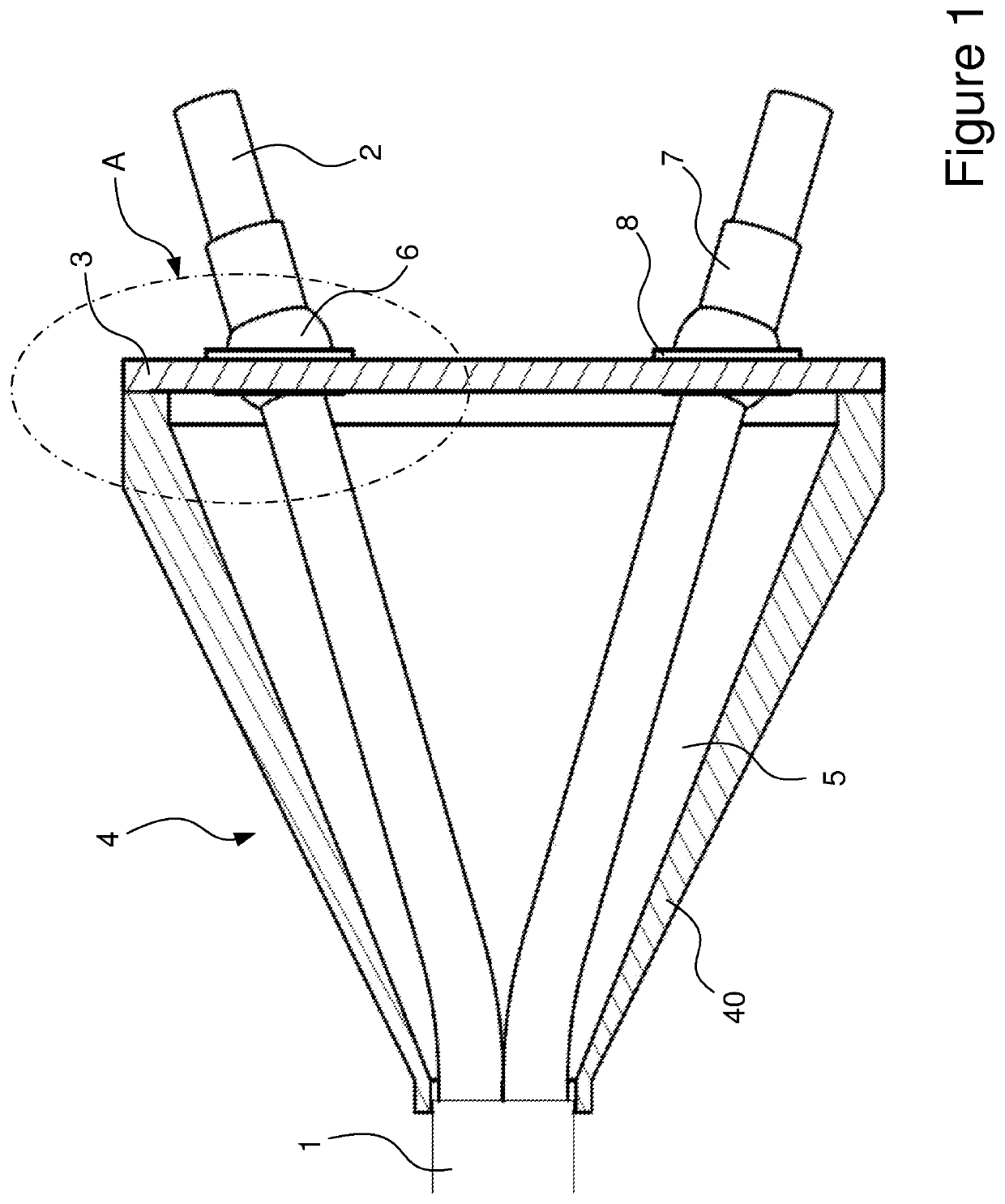
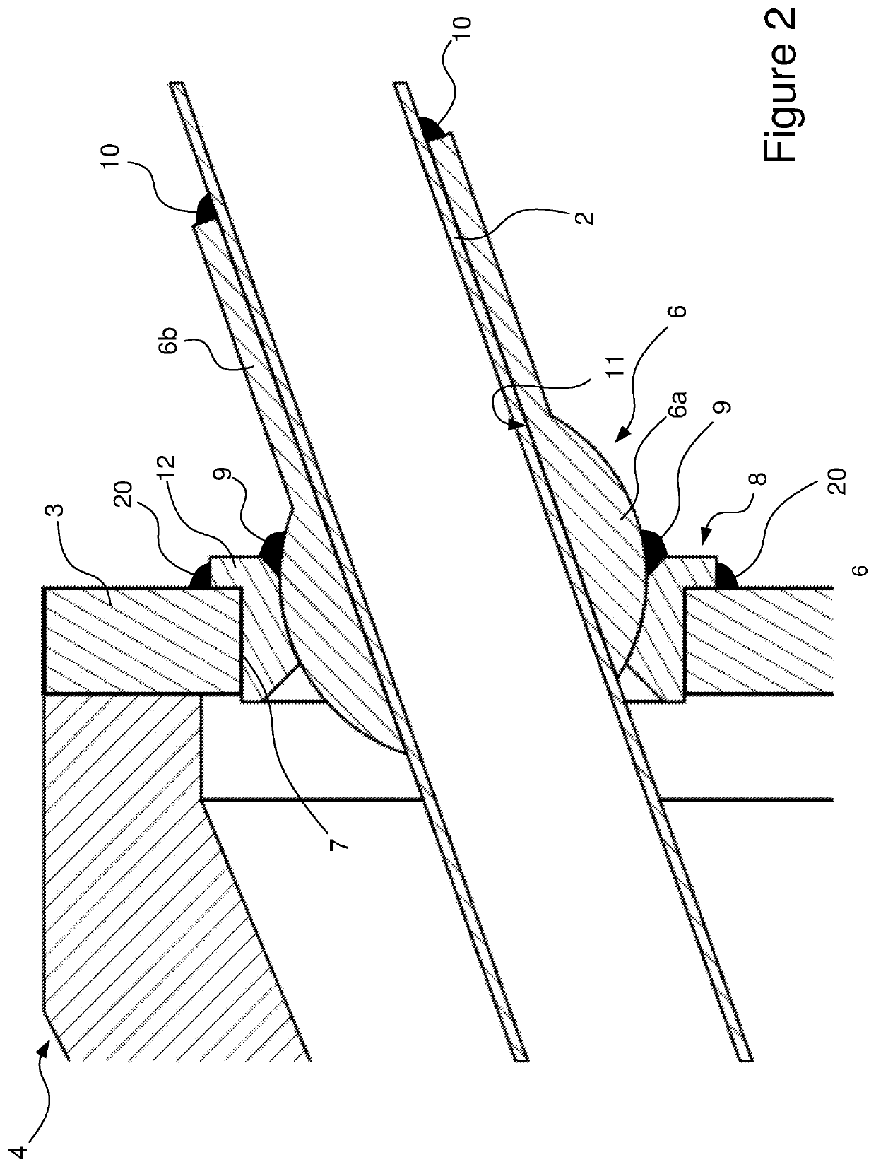
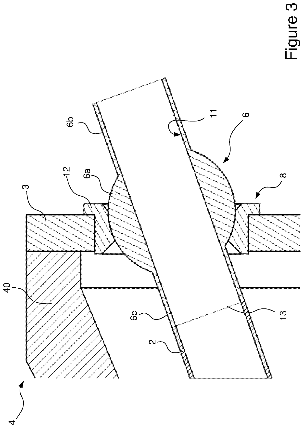
[0033]FIG. 1, shows an embodiment of a termination assembly 4 for an umbilical 1, according to the invention. In this embodiment, the umbilical termination 4 comprises a plurality of umbilical elements, although only two steel tubes 2 are shown in the figure. The tubes 2 extend from umbilical 1, through the termination cavity 5 of the termination assembly 4 and pass through respective holes in a steel bulkhead plate 3. Additional umbilical elements would also pass through the bulkhead plate 3. The bulkhead plate 3 is affixed to the termination assembly 4, to form the termination cavity 5. In the arrangement shown, the conical can portion 40 which forms the body of the termination assembly 4 may be formed in multiple parts which can be joined together.

[0034]It can be seen from FIG. 1 that the steel tubes 2 are bent through a relatively small angle close to the end of the umbilical 1 but are otherwise relatively straight. As such, minimal mechanical working of the tubes is required to...


PUM


Abstract

The invention relates to an umbilical termination assembly for terminating a cable or umbilical. The termination assembly comprises a plurality of umbilical elements extending from an umbilical and which pass through a bulkhead plate. The seated ball element has a spherical body through which an umbilical element passes. The ball element is seated in a cup member which allows the ball element to rotate through a large range of angles allowing it to be aligned with the umbilical element without the umbilical element needing to be manipulated or forced into position. The umbilical element can then be attached to the ball element which is supported by the cup member on the bulkhead. This allows the axial tension in the umbilical element to be transferred to the bulkhead.

Description

CROSS REFERENCE TO RELATED APPLICATIONS[0001]The present application claims priority to United Kingdom Application No. 1815721.4 filed Sep. 26, 2018, the entirety of the disclosure of which is expressly incorporated herein by reference.STATEMENT RE: FEDERALLY SPONSORED RESEARCH / DEVELOPMENT[0002]Not Applicable.FIELD OF THE INVENTION[0003]This invention relates to a termination assembly. In particular, it relates to a termination assembly for a cable or umbilical and a method of assembling such a termination assembly.BACKGROUND OF THE INVENTION[0004]Cables and umbilicals are generally used to supply a variety of energy forms (e.g. electrical, hydraulic, pneumatic energy etc.), signals (electrical, optical, pressure signals) or consumables to an apparatus and can be used both above and below sea level. Umbilicals may be deployed on the seabed and typically consist of a collection of one or more types of elongate active umbilical elements including electrical, pneumatic, hydraulic and c...

Claims


Application Information

Patent Timeline
IPC IPC(8): F16C11/06
CPCF16C11/0638F16D2125/587F16D2125/60B60T11/046F16C11/0671F16C11/0614F16C23/045F16L5/025F16L5/14F16L25/01F16L39/04H02G3/22F16L5/022F16L55/035F16L11/127F16L11/22
Inventor ANDERSON, LUKEWILKINSON, STEVENGRAYSON, DANIELSMEE, MIKE
Owner JDR CABLE SYST
Why Eureka
Try Eureka