Vehicular Frame's Coupler Structure

Active Publication Date: 2020-04-02
ALUMIS
View PDF0 Cites 0 Cited by
  • Summary
  • Abstract
  • Description
  • Claims
  • Application Information

AI Technical Summary

Benefits of technology

The present invention provides a vehicle frame with multiple frame components that connect to form one assembled vehicle, such as a bicycle. The coupling parts of the frames have inclined inner surfaces that prevent slippage and strengthen the overall cohesiveness of the coupler. The coupler is designed to be secure and prevent separation during use. The frame is stable even when being operated on, and the coupler structure prevents relative displacement and rotation. The coupler can accommodate several more bolts to increase strength and hardness. The unique shapes and structure of the coupler, as well as the way the frames fit together, make the vehicle less prone to sudden disassembly during use. The coupler is designed to be hidden from the rider, so the user's clothes or body will not catch on or interfere with the riding experience. The invention facilitates the assembly of multiple frames and reduces manufacturing costs.

Problems solved by technology

However, the frame of a bicycle can be large and difficult to economically ship.
However, one of the problems with the design of the frame is the high production cost that comes with the complexity of the coupler component.

Method used


Image

  • Vehicular Frame's Coupler Structure
  • Vehicular Frame's Coupler Structure
  • Vehicular Frame's Coupler Structure

Examples


Embodiment Construction

[0028]Reference is made herein to the attached drawings. Like reference numerals are used throughout the drawings to depict like or similar elements of the carrying case. For the purposes of presenting a brief and clear description of the present invention, the preferred embodiment will be discussed as used for a collapsed folding chair therein. The figures are intended for representative purposes only and should not be considered to be limiting in any respect.

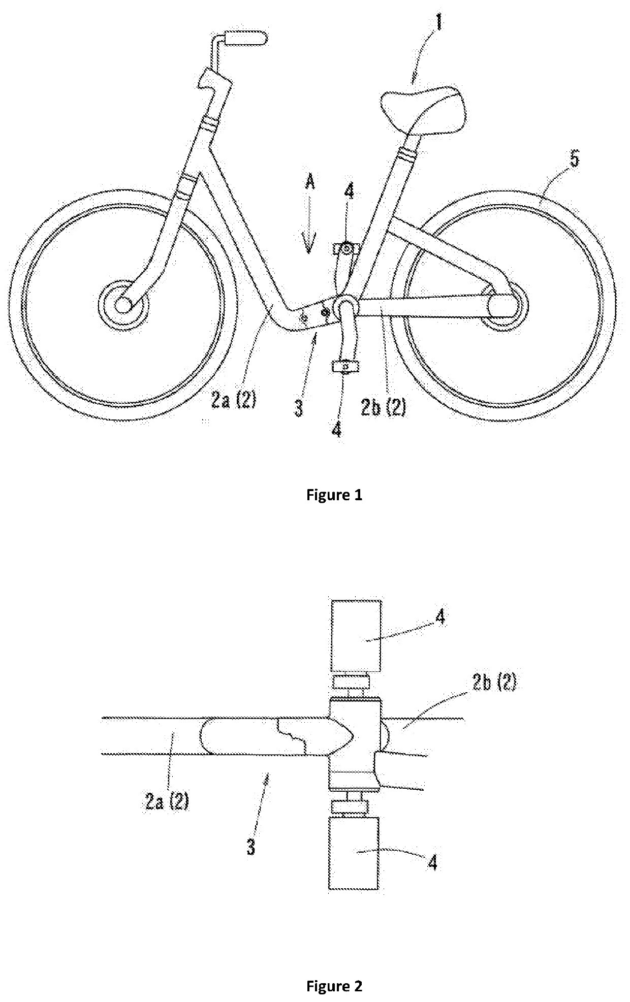
[0029]Referring now to FIGS. 1 and 2, there is shown a side view of an embodiment of the vehicle frame's coupler structure, wherein the vehicle is a bicycle and a close-up view of an embodiment of the vehicle frame's coupler structure, as seen from direction A of FIG. 1, respectively. In the illustrated embodiment, the vehicle is a bicycle having a frame 2 that is configured to be separated into two distinct parts, a front frame 2a and a back frame 2b. The vehicle frame's coupler structure 3 connects the front frame 2a to the ...


PUM


Abstract

A vehicle frame's coupler structure that connects separable frames for easy assembly and disassembly, at a low cost. Further, the couple structure can provide a vehicle that is easy to operate, without affecting the user when in use. The vehicle frame's coupler structure includes combining a Front-side Coupler Inner Face (8) with Rear-side Coupler Inner Face (9), and after making sure all components of (8) and (9) are in place (no protruding edges, etc.), and using Bolt (15) to fasten Part (6) with Part (7). The end result is the coupler system of the vehicle.

Description

CROSS REFERENCE TO RELATED APPLICATION[0001]This application claims the benefit of JP utility patent application No. 2018-186371 filed on Oct. 1, 2018, the above identified patent application is herein incorporated by reference in its entirety.BACKGROUND OF THE INVENTION[0002]The present invention uses a special interlocking mechanism, which allows a bicycle to be assembled and disassembled into different parts.[0003]Due to increased use of bicycles and similar vehicles, there is an increased demand for manufactures to ship these bicycles across the world. However, the frame of a bicycle can be large and difficult to economically ship. Therefore, there is a need to provide frames capable of disassembling into multiple parts in order to save space for storage or during shipment. When the vehicle is not in use, various parts could be disassembled, neatly packaged in the original box for easy storage or shipping. Whether it be showcasing in a store or for everyday use, the present inve...

Claims


Application Information

Patent Timeline
IPC IPC(8): B62K15/00B62K3/02
CPCB62K3/02B62K15/00B62K2015/001B62K3/06B62K19/24
Inventor TOMOHIKO, YODA
Owner ALUMIS
Why Eureka
Try Eureka