
Resource units for unassociated stations and grouped multi-user transmissions in 802.11ax networks

a resource unit and network technology, applied in the field of wireless communication networks, can solve the problems of increasing the cost of accessing the medium by the stations, consuming bandwidth, and losing more channel bandwidth, and achieve the effect of efficient use and efficient improvement of the situation

Active Publication Date: 2020-03-19
CANON KK
View PDF0 Cites 20 Cited by
  • Summary
  • Abstract
  • Description
  • Claims
  • Application Information

AI Technical Summary

Benefits of technology

The present invention aims to improve the efficiency of the use of the MU Downlink transmission from the AP. This is particularly useful when there is no AID available for a station, such as when stations are not yet associated or unassociated. The Multi-User Downlink communication protocol is enhanced to allow stations to effectively identify their RUs in this situation.

Problems solved by technology

Also, the association procedure introduced above appears to be bandwidth consuming.
As the number of BSSs increases in the same area and / or as the number of stations within a BSS substantially increases, more channel bandwidth is lost due to such SU signaling, and the cost to access the medium by the stations increases.
This is because, by failing to have an own AID, these not-yet-associated stations cannot be assigned with RUs in a MU Downlink transmission.
It remains that channel bandwidth is still wasted.
In addition, 802.11 does not provide mechanisms for multicast traffic, while the AP may receive multicast frames from an upper OSI layer, e.g. the link layer implementing Ethernet multicast.
Again, channel bandwidth is wasted.
The current operating mode of the 802.11ax multi-user feature is thus not fully satisfactory, for at least the above downsides regarding the padding bits, the SU signaling for registration and the frame duplication for multicast traffic.

Method used


Image

  • Resource units for unassociated stations and grouped multi-user transmissions in 802.11ax networks
  • Resource units for unassociated stations and grouped multi-user transmissions in 802.11ax networks
  • Resource units for unassociated stations and grouped multi-user transmissions in 802.11ax networks

Examples


Embodiment Construction

[0218]The invention will now be described by means of specific non-limiting exemplary embodiments and by reference to the figures.

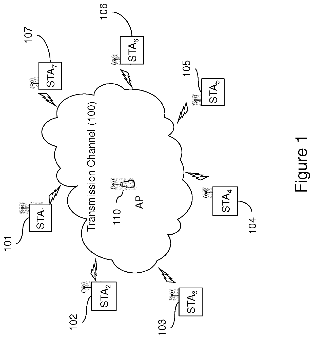
[0219]FIG. 1 illustrates a communication system in which several communication nodes (or stations) 101-107 exchange data frames over a radio transmission channel 100 of a wireless local area network (WLAN), under the management of a central station, or access point (AP) 110. The radio transmission channel 100 is defined by an operating frequency band constituted by a single channel or a plurality of channels forming a composite channel.

[0220]While the communication system of FIG. 1 shows a single physical access point 110, the AP 110 may support multiple BSSs (also called set of “virtual APs”) and be configured to manage one or more WLANs (or BSSs), i.e. one or more groups of stations. Each BSS has to be uniquely identified by a specific basic service set identification, BSSID.

[0221]To achieve this configuration, the physical AP 110 may implement two (or ...


PUM


Abstract

The invention relates to improve use of resource units in MU transmissions of an 802.1 1ax network. An un-associated station may receive data frames over a downlink resource unit, RU, assigned to an AID, e.g. 2045, reserved for stations not associated with the AP, The AP may use a downlink RU sharing an allocation scheme feature of an uplink RU previously used by the un-associated station. The AP may also aggregated data frames addressed to several stations within the same downlink RU, for instance to acknowledge frames previously received from the stations. The aggregated data frames may signal which respective response RUs the addressee stations should use for a next multi-user uplink transmission to respond to the AP. These approaches particularly applies to the exchange of management frames for instance to speed up the association procedure of un-associated stations.

Description

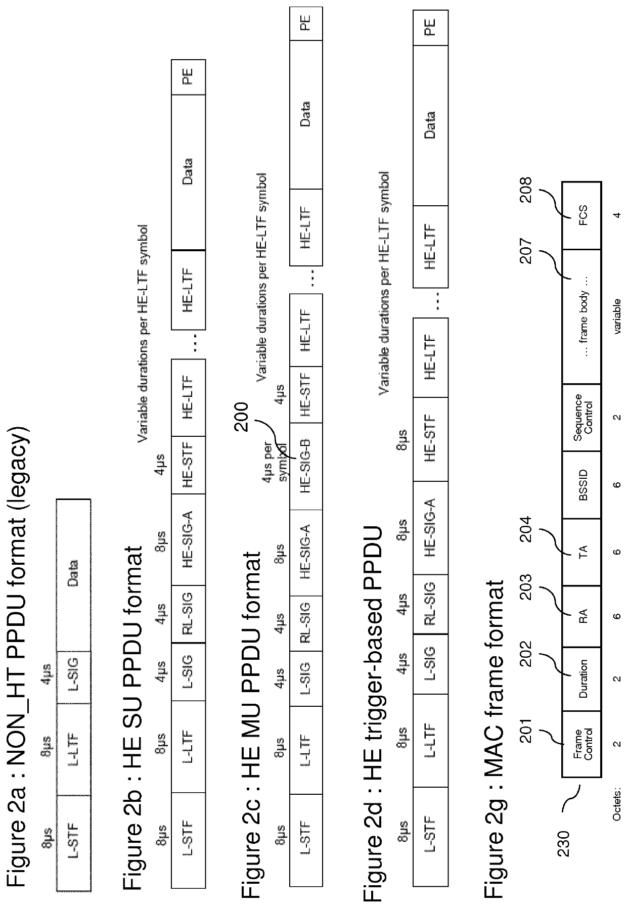
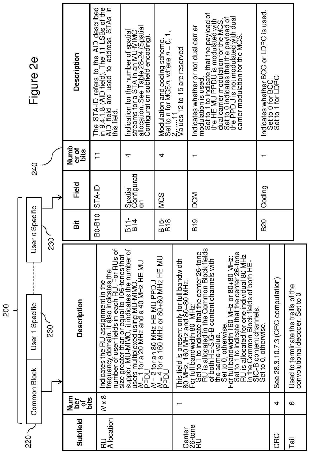
FIELD OF THE INVENTION[0001]The present invention relates generally to wireless communication networks comprising an access point (AP) and stations and more specifically to the transmission of data frames and / or acknowledgement thereof within a transmission opportunity made of sub-channels or Resource Units, and corresponding devices.[0002]The invention finds application in wireless communication networks, in particular to the access of an 802.11ax composite channel and of OFDMA Resource Units forming for instance an 802.1 lax composite channel for Downlink communication from the access point to the stations. One application of the method regards wireless data communication over a wireless communication network using Carrier Sense Multiple Access with Collision Avoidance (CSMA / CA), the network being accessible by a plurality of station devices.BACKGROUND OF THE INVENTION[0003]The IEEE 802.11 MAC family of standards (a / b / g / n / ac / etc.) defines a way wireless local area networks (WLANs)...

Claims


Application Information

Patent Timeline
Patent Type & Authority Applications(United States)
IPC IPC(8): H04W72/04H04W84/12H04W74/08H04W72/12
CPCH04W72/1257H04W72/0446H04W72/0413H04W74/0816H04W84/12H04W72/042H04W72/12H04W72/121H04W72/535H04W72/21H04W72/23
Inventor NEZOU, PATRICEVIGER, PASCALBARON, STÉPHANESEVIN, JULIEN
Owner CANON KK
Learn More