
Drill bits

a drill bit and percussion technology, applied in drill bits, drill accessories, earthwork drilling and mining, etc., can solve the problems of most likely not optimising drill bit performance, and achieve the effects of improving performance, improving wear life, and increasing work intensity

Active Publication Date: 2020-03-12
MINCON INT
View PDF0 Cites 0 Cited by
  • Summary
  • Abstract
  • Description
  • Claims
  • Application Information

AI Technical Summary

Benefits of technology

The patent text discusses the importance of certain values, called KPI1 and KPI2, in determining the performance and wear life of drill bits. A drill bit with higher KPI1 values is more durable and efficient, while a drill bit with higher KPI2 values has better performance and speed. The text also mentions that a drill bit with lower KPI3 values performs better and has longer wear life compared to a drill bit with higher KPI3 values. The optimal KPI3 value depends on the impact mechanism and rock type. This information can help create drill bits that have better performance and wear life by optimizing these values within specific ranges.

Problems solved by technology

If the KPI values are above the curve, drilling performance is most probably not optimised.

Method used


Image

  • Drill bits
  • Drill bits
  • Drill bits

Examples


example

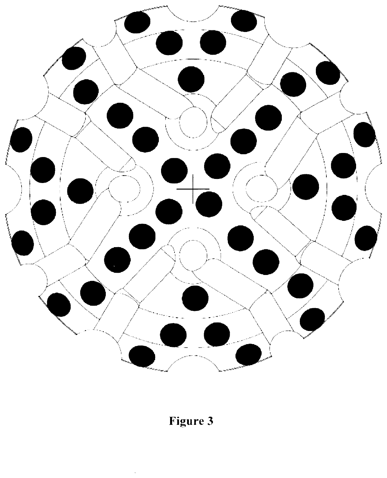
[0049]As an example, FIGS. 3, 4 and 5 show three different 165 mm diameter drill bit designs:[0050]1. BIT 1—With 40 11 mm diameter indenters[0051]2. BIT 2—With 9 19 mm diameter indenters and 12 16 mm diameter indenters.[0052]3. BIT 3—With 57 11 mm diameter indenters

[0053]Calculating the area values for these bits provides:[0054]1. BIT 1—Total bit face area: 21.382 mm2, total indenter area: 3.801 mm2, average indenter area: 95 mm2 [0055]2. BIT 2—Total bit face area: 21.382 mm2, total indenter area: 4.964 mm2, average indenter area: 236 mm2 [0056]3. BIT 3—Total bit face area: 21.382 mm2, total indenter area: 5416 mm2, average indenter area: 95 mm2

[0057]Calculating the KPI's as above for each of these bits provides the following values.

TABLE 1KPI1KPI2KPI3BIT 117.7%0.44%,534 mm2BIT 223.2% 1.1%,1,018 mm2  BIT 325.3%0.44%375 mm2

[0058]Thus, on the basis of the above calculated KPIs it can be expected that in most rock types BIT 1 will drill faster than BIT 2 as BIT 1 has a lower KPI2 and ...


PUM


Abstract

A multi-indenter drill bit comprising a plurality of indenters arranged on a drilling surface of a bit face, the ratio of the total indenter area to the bit face area being defined by a parameter KPI1 (expressed as a percentage); the ratio of the average individual indenter area to the bit face area being defined by a parameter KPI2, (expressed as a percentage) and wherein the relationship between KPI1 and KPI2 is defined by an equation.

Description

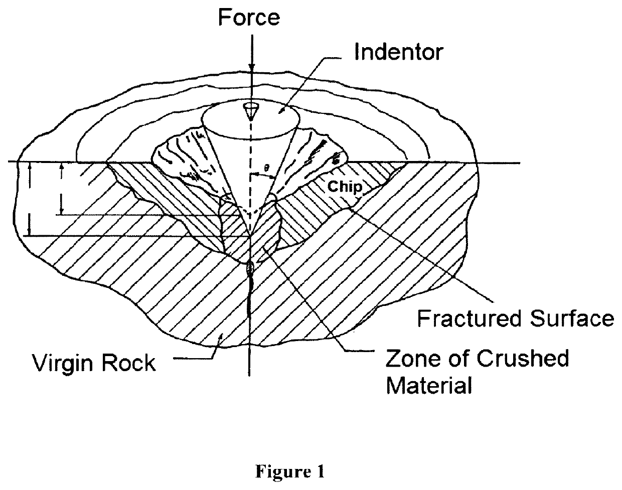
FIELD OF THE INVENTION[0001]The present invention relates to percussion drill bits and, in particular, to the size, number placement and spacing of multiple indenters on a drill bit.BACKGROUND TO THE INVENTION[0002]Modern percussion drill bits use spherical or (more or less) conical indenters (also called ‘buttons’) to remove chips from a rock mass (FIG. 1). When drilling, a network of cracks is created in the rock under an indenter when the indenter is loaded with sufficient force to substantially penetrate the rock mass and subsequently unloaded. When these cracks intersect with the free surface of the rock mass, rock chips are liberated. From a drilling productivity perspective, the applied work (i.e. force×penetration distance) per loading cycle is most efficiently utilised where the liberated chip volume / applied work ratio is as high as possible. If, for any reason, the crack network created by an indenter does not intersect the rock surface, then it does not liberate rock chip...

Claims


Application Information

Patent Timeline
Patent Type & Authority Applications(United States)
IPC IPC(8): E21B10/56E21B10/36
CPCE21B10/56E21B10/36E21B10/00
Inventor KOSOVICH, JOHN
Owner MINCON INT
Learn More