Impedance tuner and signal amplification device

a technology of impedance tuner and signal amplification, which is applied in the direction of waveguide type devices, amplifiers with transit-time effects, impedence matching networks, etc., can solve the problem that mechanically controlled impedance tuners need a lot of time to completely drive the slug

Active Publication Date: 2020-03-05
MITSUBISHI ELECTRIC CORP
View PDF0 Cites 2 Cited by
  • Summary
  • Abstract
  • Description
  • Claims
  • Application Information

AI Technical Summary

Benefits of technology

[0019]According to the present invention, because the control circuit is configured to detect the impedance of the load and control each of the reactance values of the first and second variable reactance elements and the phase shift amount of the phase shifter on the basis of the detected impedance, the present invention is effective in achieving impedance matching even with the phase shifter that performs discrete phase shift control.

Problems solved by technology

Mechanically controlled impedance tuners need a lot of time to completely drive the slug.

Method used


Image

  • Impedance tuner and signal amplification device
  • Impedance tuner and signal amplification device
  • Impedance tuner and signal amplification device

Examples


first embodiment

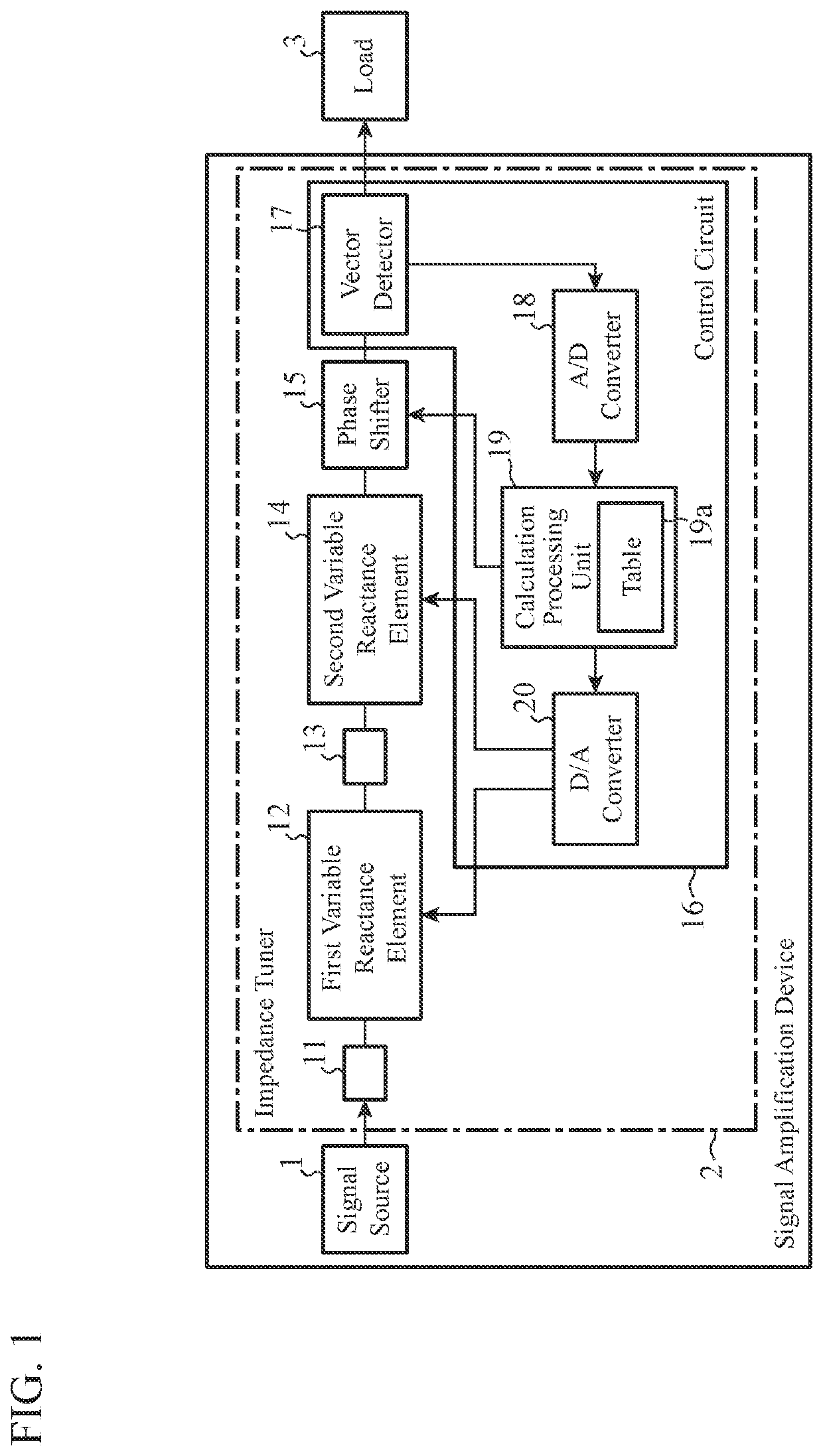
[0028]FIG. 1 is a configuration diagram illustrating a signal amplification device including an impedance tuner according to the first embodiment of the present invention.

[0029]In FIG. 1, a signal source 1 is an amplifier such as a traveling wave tube amplifier (TWTA) or a solid state power amplifier (SSPA), for example, and outputs an amplified signal to the impedance tuner 2.

[0030]The impedance tuner 2 is a device for matching the impedance of the signal source 1 and the impedance of a load 3.

[0031]The load 3 is a load whose impedance P1 is unknown.

[0032]A first transmission line 11 is a transmission line connected at one end thereof to the output end of the signal source 1 and having an electrical length of a quarter wavelength at the frequency of a signal output from the signal source 1.

[0033]A first variable reactance element 12 is a variable reactance element connected at one end thereof to the other end of the first transmission line 11.

[0034]A second transmission line 13 is ...

second embodiment

[0094]In the second embodiment, a specific configuration example of a phase shifter 30 provided in an impedance tuner will be described.

[0095]FIG. 5 is a configuration diagram illustrating the phase shifter 30 of the impedance tuner according to the second embodiment of the present invention. In FIG. 5, reference signs identical to those in FIGS. 1 and 4 designate identical or corresponding components, and the descriptions thereof are omitted.

[0096]In the same manner as the phase shifter 15 in the first embodiment above, the phase shifter 30 shifts the phase of a signal having passed through the second variable reactance element 14 and outputs the phase-shifted signal.

[0097]The phase shifter 30 includes transmission lines 31 to 40 that are connectable in series and switches 41 to 50 that select transmission lines to be connected in series from among the transmission lines 31 to 40.

[0098]The control circuit 16 controls the phase shift amount φ of the phase shifter 30 by controlling t...


PUM


Abstract

A control circuit (16) is configured to detect the impedance P1 of a load (3) and control each of the reactance value L1 of a first variable reactance element (12), the reactance value L2 of a second variable reactance element (14), and the phase shift amount φ of a phase shifter (15) on the basis of the detected impedance P1. Consequently, impedance matching can be achieved even with the phase shifter (15) that performs discrete phase shift control.

Description

TECHNICAL FIELD[0001]The present invention relates to an impedance tuner and a signal amplification device including variable reactance elements and a phase shifter.BACKGROUND ART[0002]Mechanically controlled impedance tuners are capable of matching the impedance of a signal source and the impedance of a load by driving a slug in a waveguide using a motor.[0003]Mechanically controlled impedance tuners need a lot of time to completely drive the slug.[0004]Patent Literature 1 below discloses an electronically controlled impedance tuner as a compact impedance tuner that operates faster than mechanically controlled impedance tuners.[0005]The impedance tuner disclosed in Patent Literature 1 includes a variable reactance element and a phase shifter.[0006]The phase shifter of the impedance tuner controls the phase of a signal from a signal source to a load connected to the impedance tuner in a manner as to move the impedance of the load to a point on a constant conductance circle passing t...

Claims


Application Information

Patent Timeline
Patent Type & Authority Applications(United States)
IPC IPC(8): H03H11/28H01P1/18H03F3/21H03F3/58H03F1/56
CPCH01P1/18H03F1/56H03F3/21H03F2200/423H03F3/58H03H11/28H03H7/383H03H7/185H03H7/20
Inventor NINOMIYA, DAIKUWATA, EIGONONOMURA, HIROYUKI
Owner MITSUBISHI ELECTRIC CORP
Why Eureka
Try Eureka