
Remotely-controlled magnetic surveillance and attack prevention system and method

a magnetic surveillance and attack prevention technology, applied in the field of remote control, suspended devices, can solve the problems of increasing the frequency of violent attacks on civilians, many tragic deaths and serious injuries of innocent civilians in schools, and no effective system or method is available to quickly stop, immobilize or delay an attacker

Active Publication Date: 2020-03-05
MARTIN GEOFFREY
View PDF7 Cites 5 Cited by
  • Summary
  • Abstract
  • Description
  • Claims
  • Application Information

AI Technical Summary

Benefits of technology

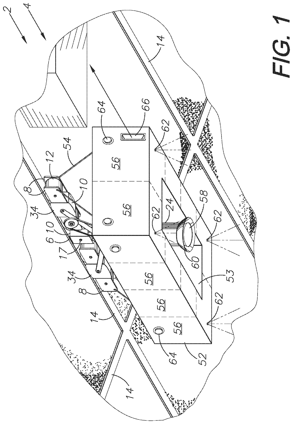
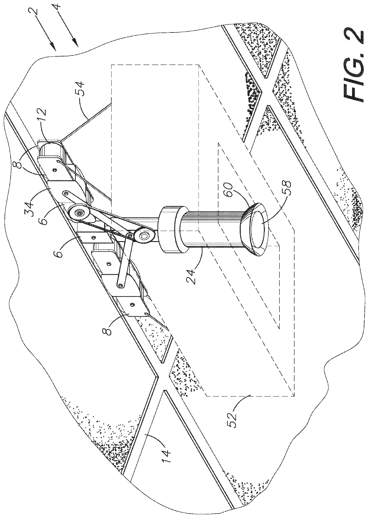
The present invention is about a system and method for surveillance and attack prevention. It includes a movable magnetic apparatus that can be remotely controlled. The apparatus can be mounted on a metal T-bar grid or track using magnets and wheels, allowing it to move along the grid or track. Additionally, there is a rotational component that allows the apparatus to move in multiple directions without needing to be removed from the mounting point. The technical effects of the invention include improved surveillance and protection against attacks.

Problems solved by technology

Unfortunately, in recent years, violent attacks on civilians have increased in frequency to the point where they have practically become commonplace.
Such attackers have used firearms, explosives, and other types of weaponry to carry out these violent attacks, creating horrific scenes which have resulted in many tragic deaths and serious injuries to innocent civilians in schools, in churches, at concerts, at bars, in movie theaters, and at various other public places.
However, currently there are not effective systems nor methods available to quickly stop, immobilize, or delay an attacker prior to the police or other authorities arriving to the scene.

Method used


Image

  • Remotely-controlled magnetic surveillance and attack prevention system and method
  • Remotely-controlled magnetic surveillance and attack prevention system and method
  • Remotely-controlled magnetic surveillance and attack prevention system and method

Examples


Embodiment Construction

I. Introduction and Environment

[0027]As required, detailed aspects of the present invention are disclosed herein, however, it is to be understood that the disclosed aspects are merely exemplary of the invention, which may be embodied in various forms. Therefore, specific structural and functional details disclosed herein are not to be interpreted as limiting but merely as a basis for the claims and as a representative basis for teaching one skilled in the art how to variously employ the present invention in virtually any appropriately detailed structure.

[0028]Certain terminology will be used in the following description for convenience in reference only and will not be limiting. For example, up, down, front, back, right and left refer to the invention as orientated in the view being referred to. The words, “inwardly” and “outwardly” refer to directions toward and away from, respectively, the geometric center of the aspect being described and designated parts thereof. Forwardly and r...


PUM


Abstract

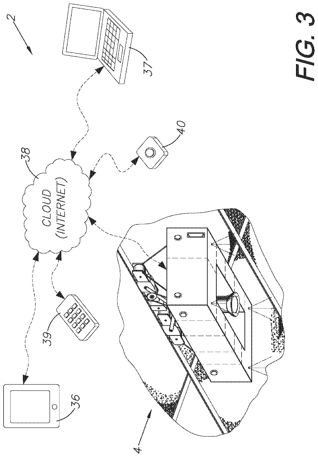
A remotely-controlled, movable, magnetic system and method for surveillance and attack prevention. The system includes a motive apparatus including a mounting body for mounting a series of magnets and wheels or rollers and suspending the apparatus from a magnetic ceiling T-bar grid or alternative metal track. The wheels or rollers make contact with the T-bars or track; provide some space between the magnets and T-bars or track; and allow for movement of the system along the T-bar grid or track. One or more of the wheels is drivingly connected to a drive motor. The system further includes a processor, an input / output interface, and a remote computing device or remote control for controlling the motive apparatus via a communications network. The motive apparatus further mounts components and tools remotely controlled by a user for observing, identifying a potential attacker, and hindering a potential attack.

Description

CROSS-REFERENCE TO RELATED APPLICATION[0001]This application claims priority in U.S. Provisional Patent Application No. 62 / 725,121, filed Aug. 30, 2018, which is incorporated herein by reference.BACKGROUND OF THE INVENTION1. Field of the Invention[0002]The present invention relates generally to remotely-controlled, suspended devices and more specifically to remotely-controlled, magnetic, suspended systems and methods for intruder attack prevention and suppression.2. Description of the Related Art[0003]Unfortunately, in recent years, violent attacks on civilians have increased in frequency to the point where they have practically become commonplace. Such attackers have used firearms, explosives, and other types of weaponry to carry out these violent attacks, creating horrific scenes which have resulted in many tragic deaths and serious injuries to innocent civilians in schools, in churches, at concerts, at bars, in movie theaters, and at various other public places. Finding solutions...

Claims


Application Information

Patent Timeline
Patent Type & Authority Applications(United States)
IPC IPC(8): G08B13/24G05B15/02G08B25/12G08B15/00G08B15/02
CPCG08B15/005G08B25/12G08B13/24G05B15/02G08B15/02G08B13/19632
Inventor MARTIN, GEOFFREY
Owner MARTIN GEOFFREY
Learn More