
Microphone Array System

a microphone array and array technology, applied in the field of microphone array systems, can solve the problems of reducing the work space of participants, reducing the distance from the speaker, and affecting the sound quality of the speaker, so as to improve the speech acquisition, reduce the setup effort, and enhance the freedom of participants

Active Publication Date: 2020-02-27
SENNHEISER ELECTRONICS GMBH & CO KG
View PDF0 Cites 24 Cited by
  • Summary
  • Abstract
  • Description
  • Claims
  • Application Information

AI Technical Summary

Benefits of technology

The invention is a system for conferences that uses microphones to improve speech acquisition and make it easier for participants to talk. The system is designed to provide more freedom to the participants and reduce the setup effort required.

Problems solved by technology

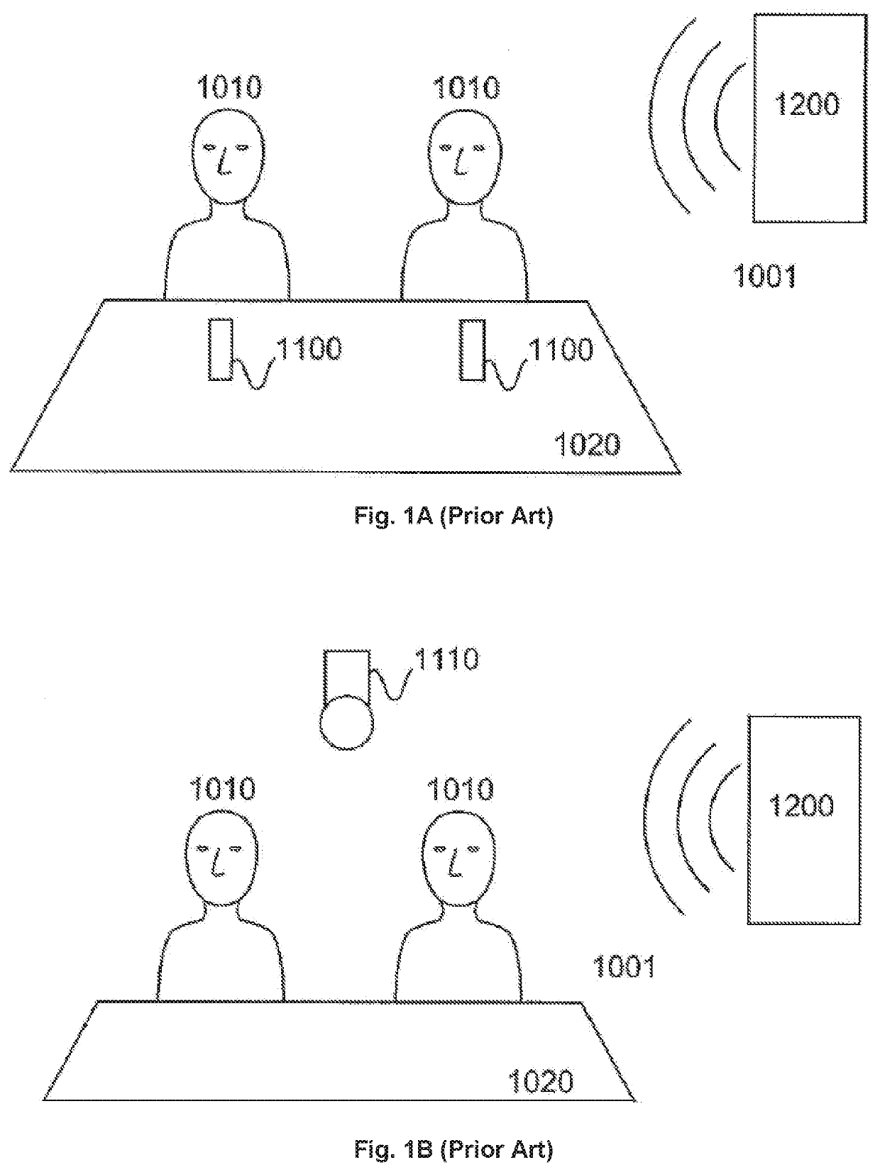
A disadvantage of this solution is the microphone 1100 requiring space on the table 1020, thereby restricting the participants work space.
If a participant 1010 walks around in the room 1001, e.g. for using a whiteboard for additional explanation, this arrangement leads to degraded speech acquisition results.
On the other hand, in this arrangement disturbing noise is always fully included in the acquired audio signal.
Furthermore, the omnidirectional directivity pattern results in noticeable signal to noise level degradation at increased distance from the speaker to the microphone.
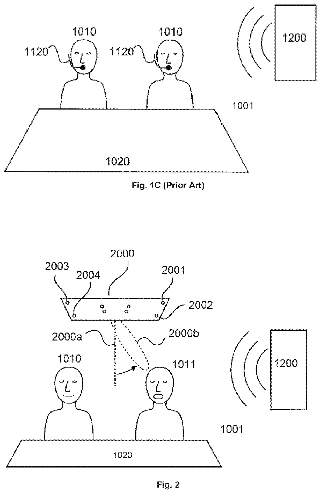
A significant disadvantage of this third solution consists in a protracted setup procedure for equipping every participant with a microphone and for connecting the microphones to the conference system.

Method used


Image

  • Microphone Array System
  • Microphone Array System
  • Microphone Array System

Examples


Embodiment Construction

[0045]It is to be understood that the figures and descriptions of the present invention have been simplified to illustrate elements that are relevant for a clear understanding of the present invention, while eliminating, for purposes of clarity, many other elements which are conventional in this art. Those of ordinary skill in the art will recognize that other elements are desirable for implementing the present invention. However, because such elements are well known in the art, and because they do not facilitate a better understanding of the present invention, a discussion of such elements is not provided herein.

[0046]The present invention will now be described in detail on the basis of exemplary embodiments. It is to be noted that the terms microphone array unit and microphone array system are used synonymously herein.

[0047]FIG. 2 shows a schematic representation of a conference room with a microphone array system according to the invention. A microphone array 2000 can be mounted ...


PUM


Abstract

A microphone array system or microphone array unit for a conference system is provided that includes a front board, side walls and a plurality of microphone capsules arranged in or on the front board mountable on or in a ceiling of a conference room. The microphone array system or unit is adapted for generating a steerable beam within a maximum detection angle range. The microphone array system or microphone array unit includes a processing unit which is configured to receive the output signals of the microphone capsules and to steer the beam based on the received output signal of the microphone array. The processing unit is configured to control the microphone array to limit the detection angle range to exclude at least one predetermined exclusion sector in which a noise source is located.

Description

[0001]The present application is a continuation-in-part of U.S. patent application Ser. No. 15 / 780,787 which is a national phase of International Patent Application No. PCT / EP2016 / 079720 filed on Dec. 5, 2016, which claims priority from U.S. patent application Ser. No. 14 / 959,387 filed on Dec. 4, 2015, the disclosures of which are incorporated herein by reference in their entirety.FIELD OF THE INVENTION[0002]It is noted that citation or identification of any document in this application is not an admission that such document is available as prior art to the present invention.[0003]The invention relates to a microphone array system that may be used in a conference system.[0004]In a conference system, the speech signal of one or more participants, typically located in a conference room, must be acquired such that it can be transmitted to remote participants or for local replay, recording or other processing.[0005]FIG. 1A shows a schematic representation of a first conference environme...

Claims


Application Information

Patent Timeline
Patent Type & Authority Applications(United States)
IPC IPC(8): H04R1/40H04R3/04H04R3/00
CPCH04R2201/405H04R3/04H04R3/005H04R2201/401H04R2430/23H04R1/406H04R2201/021H04M3/56H04M2203/509
Inventor ROLLOW, IV, J. DOUGLASREICHERT, LANCEVOSS, DANIEL
Owner SENNHEISER ELECTRONICS GMBH & CO KG
Learn More