
Pipe joint

Pending Publication Date: 2020-02-20
MANNING JOHN PATRICK +1
View PDF0 Cites 0 Cited by
  • Summary
  • Abstract
  • Description
  • Claims
  • Application Information

AI Technical Summary

Benefits of technology

The invention concerns a pipe joint that includes an anchoring element to transmit or transfer loading force between two conduit sections. The anchoring element has a bridging portion with sufficient size and strength to distribute the loading force evenly between the anchoring portions, reducing the strain on any one portion. This is particularly useful when the tolerances of the positioning of grooves or channels in the conduit sections are large. The anchoring element can be easily disassembled for disconnection of the conduit sections without damaging them. This simplifies the process of connecting and disconnecting the pipe joint.

Problems solved by technology

However, welded joints have a disadvantage of requiring skilled workers to form them, as well as having negative health and safety and environmental implications.
Also, around 1 in 10 of such welded joints typically may need some repair after such inspection.
All this makes oil and gas pipelines particularly expensive and time consuming to construct and maintain.
A further problem with both press-fit and welded joints is that they are difficult to disconnect, for example for repair or maintenance, and once disconnected they are generally not re-useable.
Furthermore, disconnection of press-fit or welded joints often results in damage to the pipe lengths themselves.
However, in practice such joints have limited efficacy and longevity, in particular when the jointed pipe lengths are subjected, as is common in many fluid transport systems, to high internal fluid pressures and / or repeated pressure pulsing of the pumped fluid.
In such cases a new problem which occurs over time is that wear occurs of the material defining and surrounding the grooves in the respective pipe walls, which leads to reductions in the wall thicknesses at the groove sites, which ultimately can lead to failure of the pipe walls themselves in the vicinity of the joint.
This problem is exacerbated by the increasingly attractive move away from steel pipes and towards using pipes made of plastics materials, which often may not be as hard, tough or hard-wearing as steel, especially when used in conjunction with metal jointing wires.
A further problem is that repetitive strain of the flexible elongate jointing wire itself used to form the joint leads to weaknesses in the wire itself, which can thus lead to failure of the sole means which axially secures the pipe lengths together, which again can lead to failure of the overall joint.
It is not a practical solution to the above problems simply to employ thicker pipe walls and / or thicker jointing wires, because this would be very uneconomical, not only from the point of view of requiring greater amounts of materials with increased weight, bulk and cost, but it would also reduce the internal volume of, and thus fluid-carrying capacity of, the pipe.
And in any event this would by no means be a complete, efficient or long-term solution to the underlying problem of joint component wear, since such would still occur under commonly encountered high pressures and pulsed pressure loadings of the joint under typical working conditions.
Furthermore, it is also not a practical solution to the above problems to simply employ a “double-joint” (or even a “triple-” or “quadruple-” etc joint), in which two or more like wire-in-grooves type joints, axially spaced apart a short distance, each based on a respective resiliently flexible elongate wire inserted into a respective pair of mutually opposed grooves in the pipe walls to be jointed, are employed in an attempt to axially spread and thus reduce the axial loadings that occur on each joint.
This is because the typical practical engineering tolerances in the accuracy of the axial positioning of such plural sets of grooves in the respective pipe walls (especially over their entire circumference and as between different pipe sections) that such an arrangement would demand in order to work properly would be generally too great.
This would therefore defeat the underlying object of spreading load between the plural joints, and would still be a particular problem in the case of repetitive pulsed loadings.
Attempting to reduce engineering tolerances in order to address this issue is not a practical option, since that would place too great a demand on typical pipe manufacturing techniques and machinery, and would if anything, even if achievable to an acceptable degree in principle (which is technically unlikely), lead to unacceptably increased levels of cost.

Method used


Image

  • Pipe joint
  • Pipe joint
  • Pipe joint

Examples


Embodiment Construction

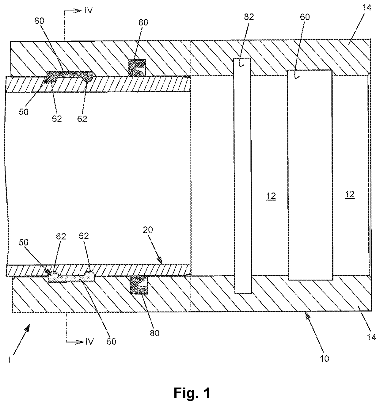
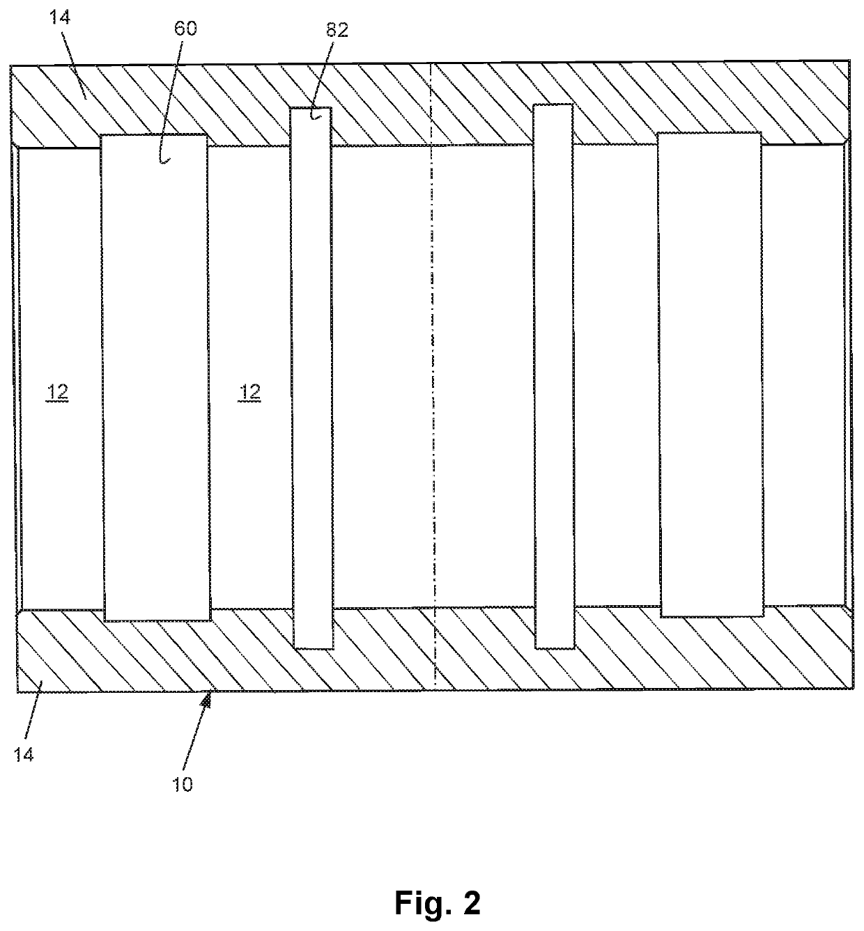
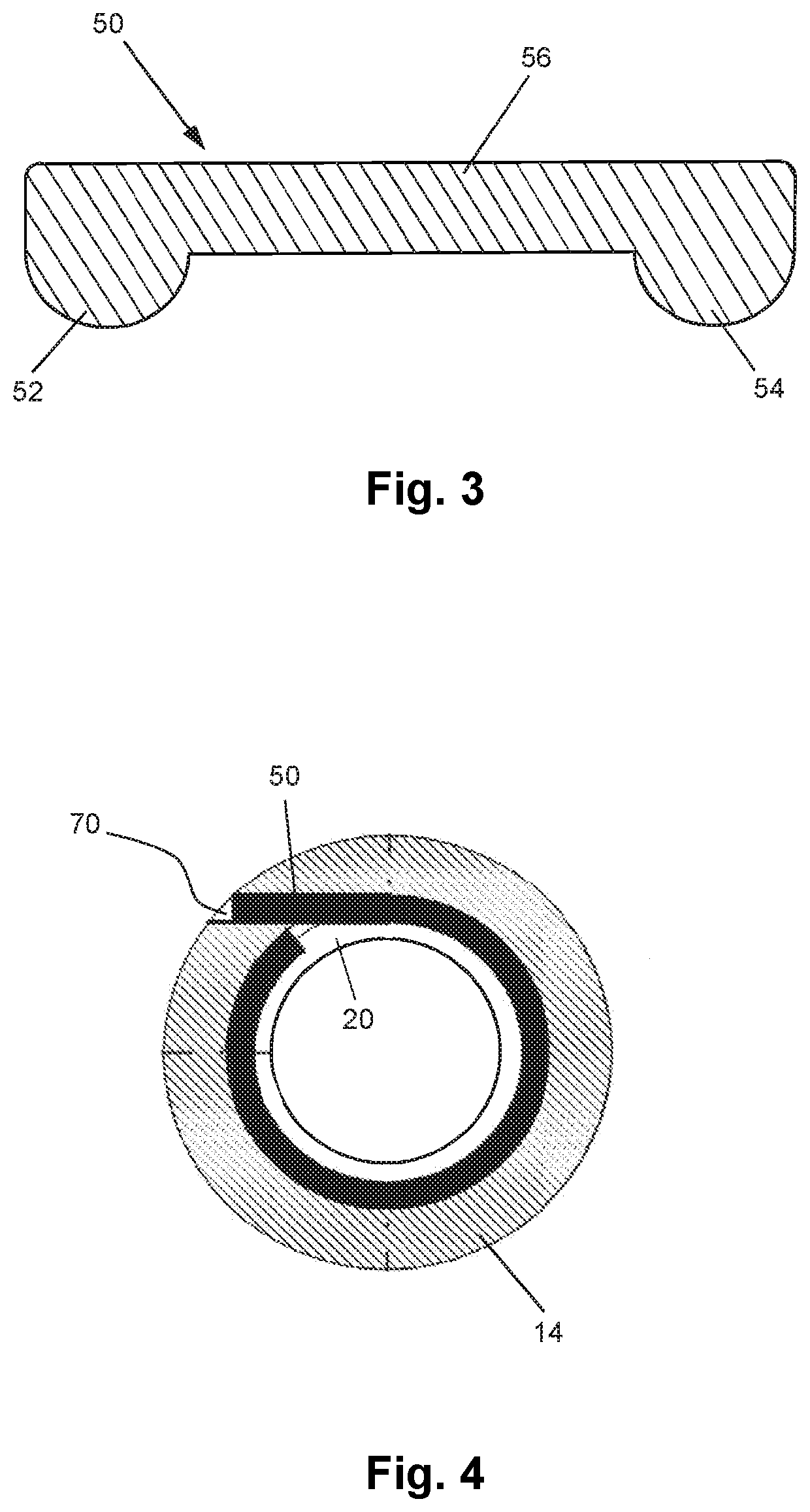
[0073]Referring firstly to FIG. 1, the pipe (or conduit) joint shown generally as 1 is formed between a first, or female, conduit or pipe section 10 and a second, or male, conduit or pipe section 20 of smaller diameter than the first section 10. The walls 14 of a connection end of the first conduit section 10 form and define a receiving recess 12 for receiving therein a connection end of the second conduit section 20. The joint 1 is formed once the connection end of the second conduit section has been inserted into the receiving recess 12 of the connection end of the first conduit section 10. The pipe (or conduit) sections 10, 20 are formed e.g. of a plastics material, or alternatively of a metal or metal alloy, depending for example on the practical application of the pipe (or conduit) and, in particular, the material to be conveyed by it.

[0074]In a typical example the pipe or conduit sections form part of a pipe or pipeline for conveying liquid or gaseous fluids, such as oil or ga...


PUM


Abstract

A pipe joint for joining pipe sections via a receiving recess at one end of the first pipe section, comprising a first groove formed in an internal wall of the receiving recess and accessible via a transverse insertion passage, a plurality of axially spaced-apart second grooves formed in an external wall of a connection end of the second pipe section, and an elongate flexible anchoring strip comprising a plurality of axially spaced-apart anchoring portions placeable in respective ones of the second grooves, wherein, once the first and plurality of second grooves have been brought into alignment upon insertion of the connection end of the second pipe section into the receiving recess, the anchoring strip is inserted from outside the first pipe section into the first groove and plurality of second grooves so as to be seated therein, thereby uniting and axially locking together the first and second pipe sections.

Description

TECHNICAL FIELD[0001]This invention relates to a joint for pipes and other conduits. More particularly, though not exclusively, the invention relates to a joint for joining together plural lengths of pipe or other conduit, for example in the forming of a fluid transport system.BACKGROUND AND PRIOR ART[0002]As used herein the term “pipe” is to be construed broadly, and is to be understood as encompassing any form, shape and size of conduit, particularly a tubular conduit. Indeed the terms “pipe” and “conduit” may be used interchangeably herein. Such pipes or conduits to which the invention may be applied may in particular include pipes or conduits having any suitable or desired cross-sectional size (e.g. diameter) and / or longitudinal length.[0003]Fluid transport systems are well-known for conveying flowable materials such as liquids and gases, with common examples including water and fuels, for example gas and oil. Such systems may include oil and gas pipelines for conveying fuel ove...

Claims


Application Information

Patent Timeline
IPC IPC(8): F16L37/14
CPCF16L17/035F16L37/148F16L37/14
Inventor MANNING, JOHN PATRICKMITCHELL, HENRY
Owner MANNING JOHN PATRICK
Learn More