Eureka AIR delivers breakthrough ideas for toughest innovation challenges, trusted by R&D personnel around the world.

A gantry-type three dimensional printing apparatus for printing a three dimensional work piece in a layer wise manner

a three-dimensional printing and layer wise technology, applied in the direction of additive manufacturing, applying layer means, manufacturing tools, etc., can solve the problems of limited working space, limited freedom of manipulation of the printing head unit, and otherwise extremely difficult to be fabricated through traditional means

Inactive Publication Date: 2020-02-13
BLACKBELT HLDG BV
View PDF1 Cites 11 Cited by
  • Summary
  • Abstract
  • Description
  • Claims
  • Application Information

AI Technical Summary

Benefits of technology

The invention aims to solve the problem of printing complex or detailed features on three dimensional work pieces that are large or long. The conveyor belt is made from a fiber composite cloth that is impregnated with epoxy resin to provide a stable support area and good heat dissipation. The support platform can create a vacuum or under pressure to prevent displacement of the work piece during printing. The heating elements prevent unwanted deformation and increase adhesion between the work piece and the conveyor belt. The printing head unit has a cone-shaped nozzle that allows for accurate positioning close to the work piece without touching it. This allows for printing of complex or detailed features on the work piece.

Problems solved by technology

With the development of sophisticated designing programming tools three dimensional work pieces can be made, which were otherwise extremely difficult to be fabricated through traditional means, if not impossible.
A drawback, however, of the known XYZ-gantry-type three dimensional printing apparatuses is the limited working space defined by the XYZ-gantry and as such the limited freedom of manipulation of the printing head unit within said working space and subsequent the limited dimensional size of the work pieces thus printed.
In particular printing work pieces with a considerable longitudinal dimension suffer from all types of disturbances, such as material instability or vibrations, which will adversely affect the final quality of the work piece when depositing molten building material in a malleable state in subsequent layers on each other.

Method used


Image

  • A gantry-type three dimensional printing apparatus for printing a three dimensional work piece in a layer wise manner
  • A gantry-type three dimensional printing apparatus for printing a three dimensional work piece in a layer wise manner
  • A gantry-type three dimensional printing apparatus for printing a three dimensional work piece in a layer wise manner

Examples


Embodiment Construction

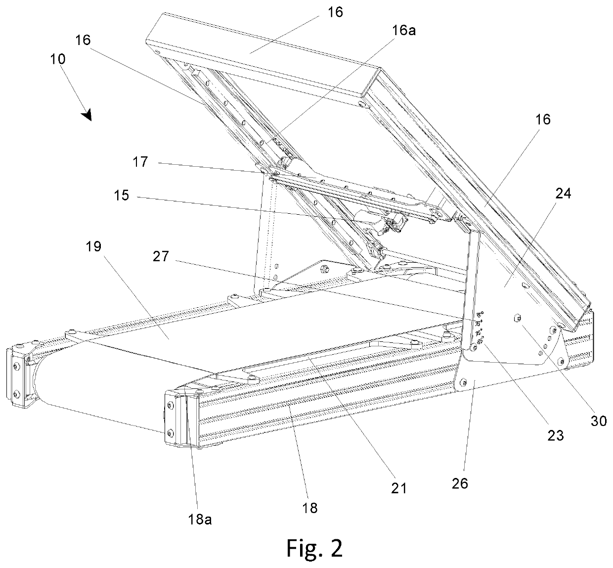
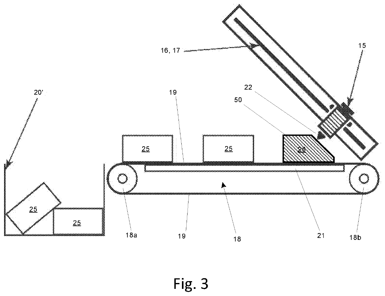
[0006]The invention aims to provide a solution for the above identified problem, allowing the printing in a layer wise manner of three dimensional work pieces having more complex or detailed features as well as work piece of considerable size or length.

[0007]According to the invention, the printing head unit is movable within a XY-plane being inclined relative to the Z-direction and wherein the support platform is composed as an endless conveyor belt oriented parallel with the horizontal.

[0008]In an example of the gantry-type three dimensional printing apparatus the conveyor belt is made from a fiber composite cloth, and more in particular said fiber composite cloth is impregnated with an epoxy resin. Herewith a stable support area is obtained, which not only stabilizes the three dimensional work piece during its layer wise built up, but moreover a good heat dissipation is obtained thus preventing printing errors due to collapsing or slumping in of the building material being printe...


PUM

PropertyMeasurementUnit
angleaaaaaaaaaa
angleaaaaaaaaaa
angleaaaaaaaaaa

Abstract

The invention relates to a gantry-type three dimensional printing apparatus for printing a three dimensional work piece in a layer wise manner using a building material, said apparatus comprising at least: a frame with an XYZ-gantry; a printing head unit coupled to said XYZ-gantry; a building material supply unit for feeding building material to said printing head unit; and a support platform on which said three dimensional work piece is being printed in layers, said support platform being part of said XYZ-gantry and is movable in the Z-direction.

Description

FIELD OF THE INVENTION[0001]The invention relates to a gantry-type three dimensional printing apparatus for printing a three dimensional work piece in a layer wise manner using a building material, said apparatus comprising at least: a frame with an XYZ-gantry; a printing head unit coupled to said XYZ-gantry; a building material supply unit for feeding building material to said printing head unit; and a support platform on which said three dimensional work piece is being printed in layers, said support platform being part of said XYZ-gantry and is movable in the Z-direction.BACKGROUND OF THE INVENTION[0002]Gantry-type three dimensional printing apparatuses for printing a three dimensional work piece in a layer wise manner have been developed over the recent years as a fast, and relative inexpensive technology to create three dimensional work pieces, which work pieces otherwise would have required the implementation of expensive and time consuming molding and casting techniques.[0003...

Claims


Application Information

Patent Timeline
Patent Type & Authority Applications(United States)
IPC IPC(8): B29C64/245B29C64/25B29C64/209B29C64/232B29C64/236B29C64/379B29C64/295
CPCB29C64/232B29C64/25B29C64/245B29C64/236B29C64/379B29C64/295B33Y30/00B33Y40/00B29C64/209B33Y80/00B33Y10/00B29C64/20B29C64/118B29C64/227
Inventor SCHÜRMANN, STEPHAN
Owner BLACKBELT HLDG BV
Why Eureka
Eureka Blog
Learn More