
Linear actuator

Inactive Publication Date: 2020-02-06
NIDEC SANKYO CORP
View PDF0 Cites 1 Cited by
  • Summary
  • Abstract
  • Description
  • Claims
  • Application Information

AI Technical Summary

Benefits of technology

The present invention provides a viscoelastic body between a fixed body and a movable body to stabilize the damper characteristic and prevent peeling of the viscoelastic body. This viscoelastic body applies a substantially constant restoring force to the movable body throughout the entire body when it undergoes shear deformation. This results in a small change in the restoring force received by the movable body from the viscoelastic body when it moves, allowing for proper driving of the movable body. The viscoelastic body is fixed to the fixed body side and the movable body side without generating a gap or likelihood of peeling. The fixed body side and the movable body side are facing parallel, further stabilizing the damper characteristic.

Problems solved by technology

However, in the above-mentioned linear actuators, there is a resonance point peak resulting from the spring member, and at this resonance point peak, there is a possibility that the movable body excessively displaces to collide with the fixed body.

Method used


Image

  • Linear actuator
  • Linear actuator
  • Linear actuator

Examples


embodiment

(Operation and Main Effect of Present Embodiment)

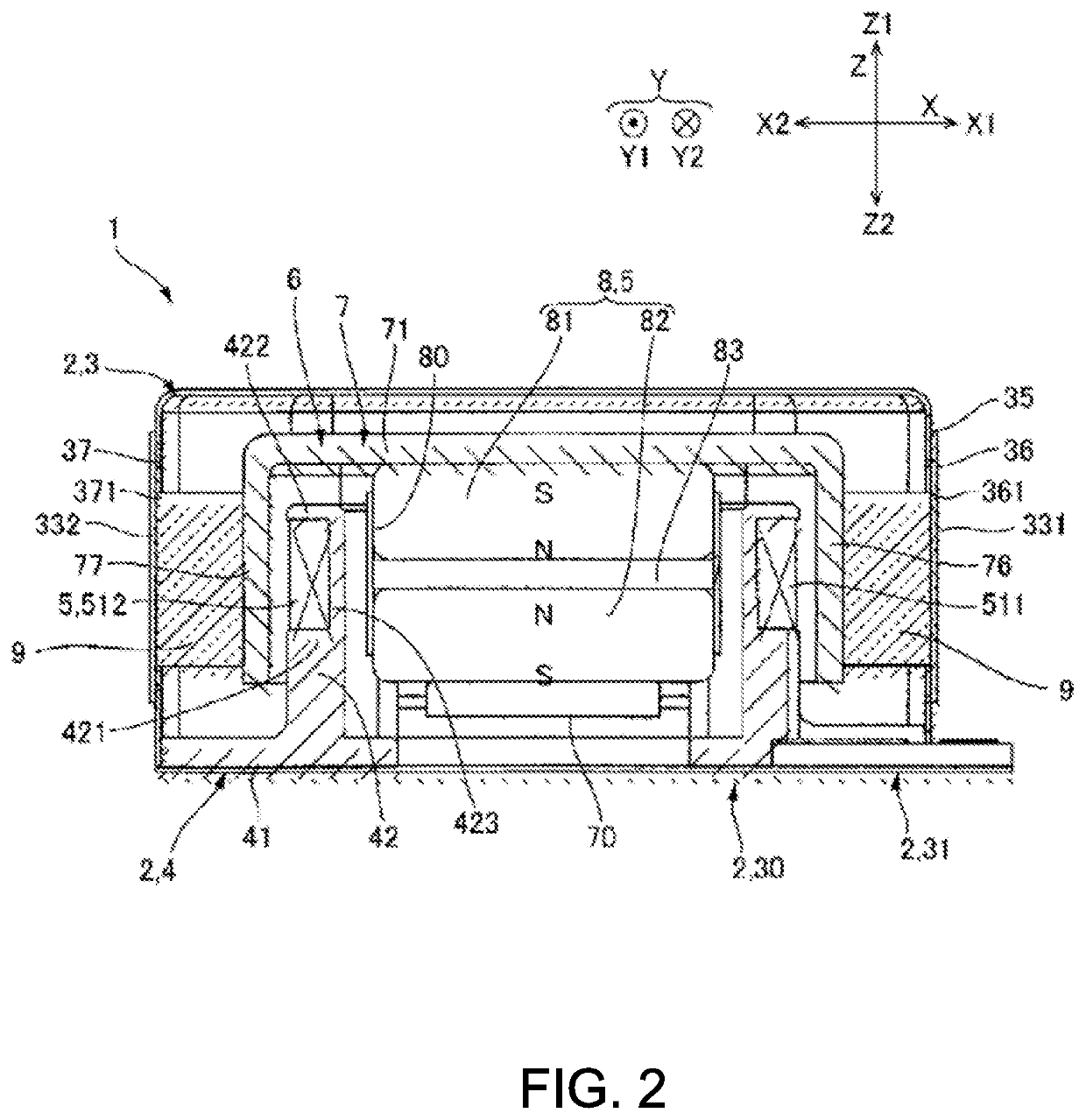
[0044]In the linear actuator 1 of the present embodiment, the movable body 6 is at an origin position where a mass of the movable body 6 and a shape holding force of the viscoelastic body 9 are balanced during a period while energization to the coil 51 is suspended. In this state, if a sinusoidal wave, an inverted pulse or the like is supplied to the coil 51, the movable body 6 receives a propulsive force by the magnetic drive mechanism 5, and moves to one side Z1 in the drive direction Z against the shape holding force of the viscoelastic body 9. As a result, the viscoelastic body 9 undergoes shear deformation. An amount of movement of the movable body 6 at that time is defined by a current value supplied to the coil 51 and a restoring force of the viscoelastic body 9. If the energization to the coil 51 is stopped, the movable body 6 returns to the origin position by the restoring force of the viscoelastic body 9.

[0045]Next, if a sin...


PUM


Abstract

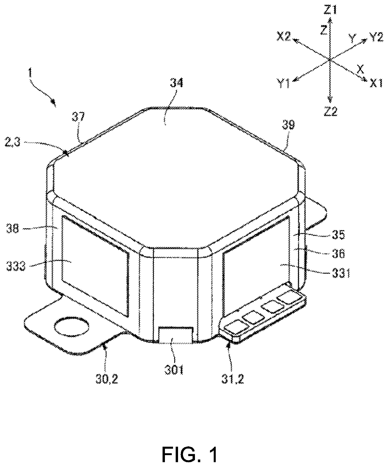
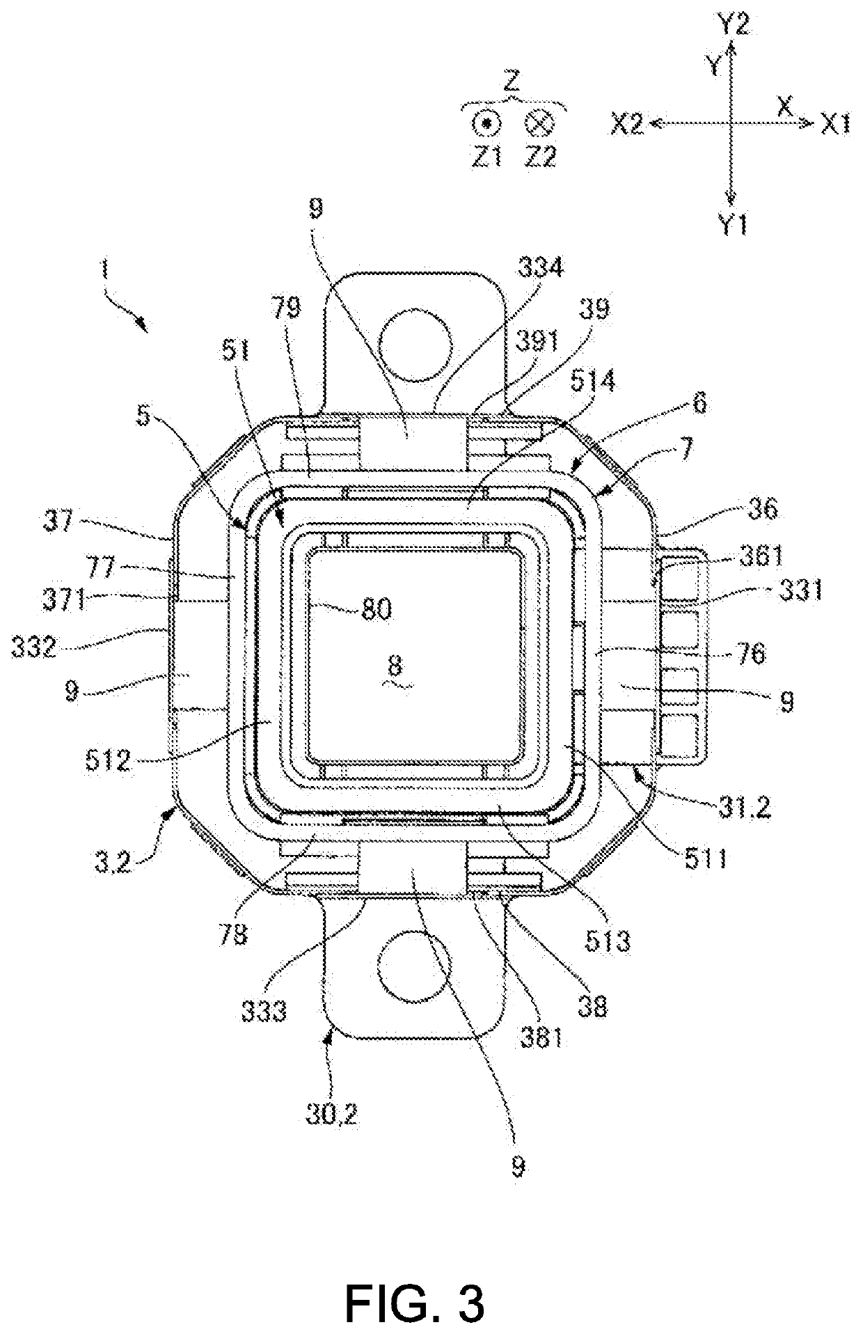
A linear actuator can properly drive a movable body even if a viscoelastic body is provided between the movable body and a fixed body. For example, a linear actuator 1 includes a fixed body 2, a movable body 6, a magnetic drive mechanism 5 configured to linearly drive the movable body 6 with respect to the fixed body 2, and a viscoelastic body 9 made of a silicone gel or the like where the viscoelastic body 9 is arranged between the fixed body 2 and the movable body 6. In a case 3 of the fixed body 2 and a first yoke 7 of the movable body 6, the viscoelastic body 9 is arranged between a fixed body side flat surface unit (such as a first fixed plate 331 and a second fixed plate 332) facing parallel to a first direction and a second direction Y orthogonal to a drive direction Z by the magnetic drive mechanism 5 and a movable body side flat surface unit (such as a first side plate unit 76 and a second side plate unit 77). Therefore, when the movable body 6 is driven, the movable body 6 undergoes shear deformation.

Description

TECHNICAL FIELD[0001]The present invention relates to a linear actuator configured to linearly drive a movable body.BACKGROUND ART[0002]In the field of mobile telephones and the like, a device for notifying an incoming call and the like by vibration is employed, and as such a device, a linear actuator in which a movable body is supported on a fixed body via a spring member can be employed (see Patent Documents 1 and 2). In the linear actuator described in Patent Documents 1 and 2, the movable body is driven in an axial direction by a magnet provided at a movable body side and a coil provided at a fixed body side. However, in the above-mentioned linear actuators, there is a resonance point peak resulting from the spring member, and at this resonance point peak, there is a possibility that the movable body excessively displaces to collide with the fixed body.[0003]On the other hand, to suppress a resonance peak of the movable body, it has been proposed to arrange a silicone gel (visco...

Claims


Application Information

Patent Timeline
IPC IPC(8): H02K33/18H02K33/16
CPCB06B1/045H02K33/18H02K33/16B06B1/04H02K33/02
Inventor TAKEDA, TADASHIKITAHARA, HIROSHITSUCHIHASHI, MASAO
Owner NIDEC SANKYO CORP
Learn More