
Method of crimping terminal with cable and terminal crimping apparatus

a technology of crimping terminal and cable, which is applied in the direction of connection contact material, line/current collector details, and permanent deformation connections, etc., can solve the problem of long manufacturing line, and achieve the effect of reducing cost and improving productivity

Active Publication Date: 2020-01-16
YAZAKI CORP
View PDF0 Cites 0 Cited by
  • Summary
  • Abstract
  • Description
  • Claims
  • Application Information

AI Technical Summary

Benefits of technology

The present invention provides a high-productivity and inexpensive method of crimping a terminal with a cable, and a terminal crimping apparatus in which anticorrosion treatment is performed on a core wire of a cable exposed from an insulating sheath within the terminal crimping apparatus in a short time. This improves productivity and reduces cost of the terminal with a cable subjected to the anticorrosion treatment.

Problems solved by technology

However, the conventional method of manufacturing a terminal with a cable has a problem in that each step is provided independently and therefore a manufacturing line becomes long.

Method used


Image

  • Method of crimping terminal with cable and terminal crimping apparatus
  • Method of crimping terminal with cable and terminal crimping apparatus
  • Method of crimping terminal with cable and terminal crimping apparatus

Examples


first embodiment

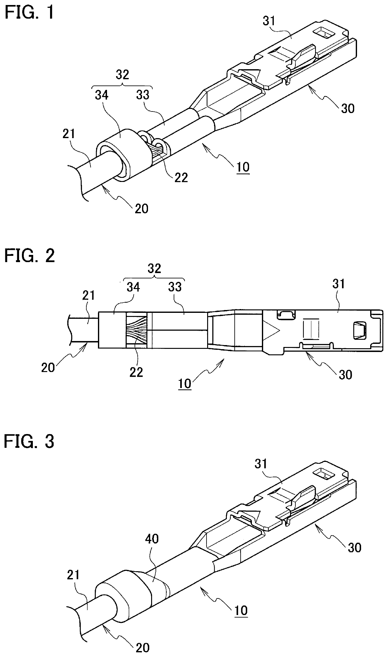
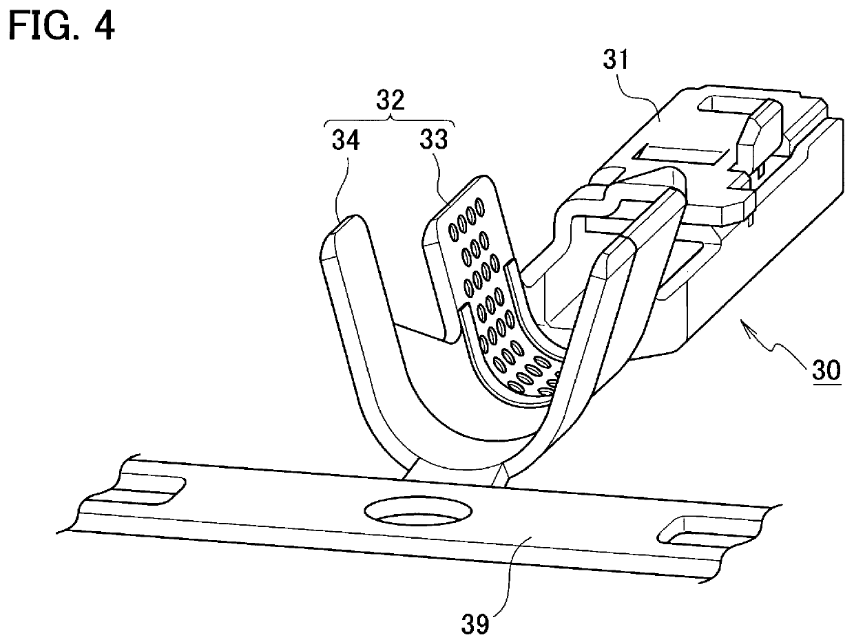
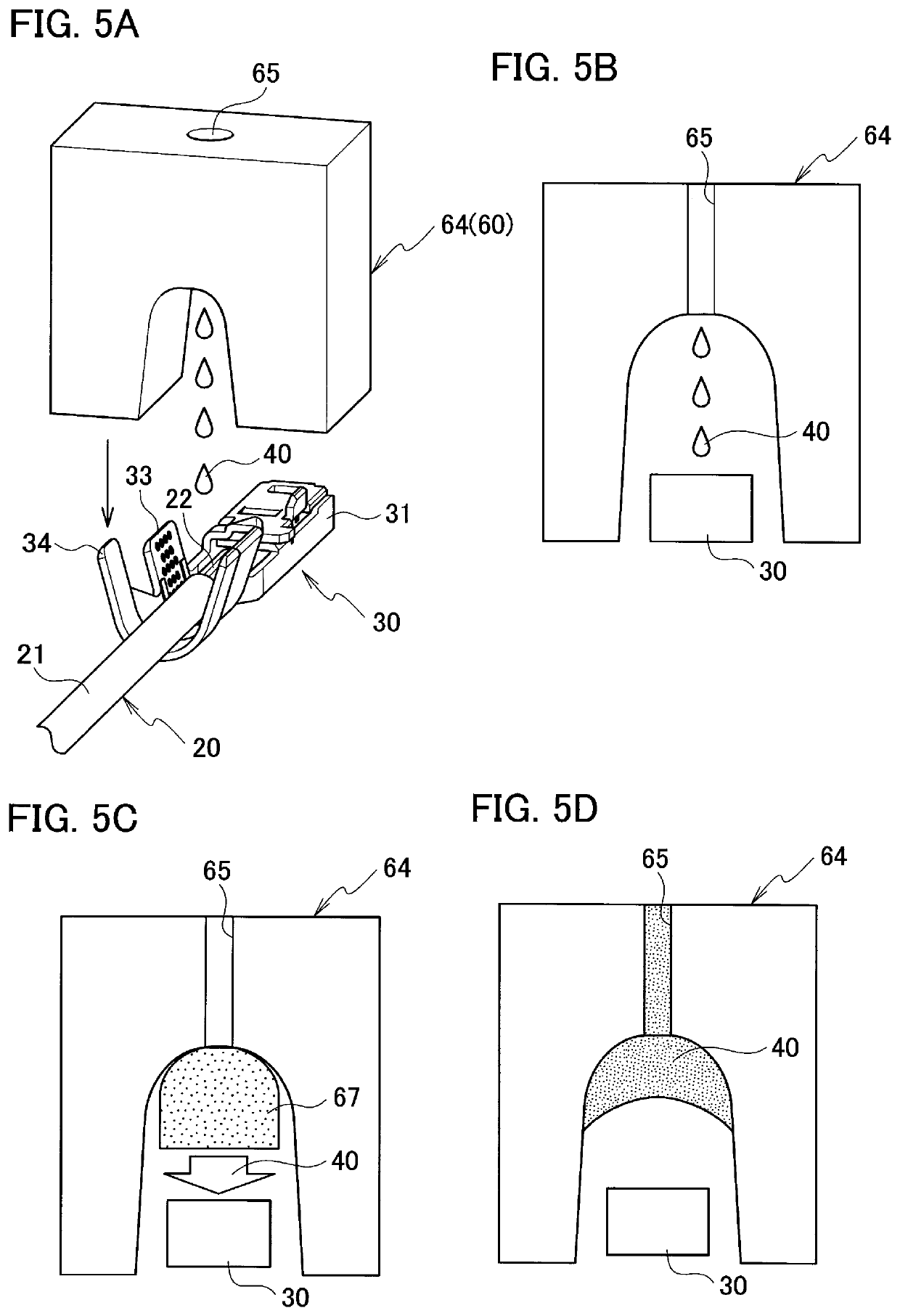
[0034]A first embodiment will be described with reference to FIGS. 1 to 13.

[0035]As illustrated in FIGS. 1 and 2, a terminal 10 with a cable includes a cable 20 and a crimp terminal 30 made of metal. In the cable 20, a core wire 22 is covered with an insulating sheath 21. The crimp terminal 30 has a box-shaped terminal connection portion 31 and a crimping portion 32.

[0036]The terminal connection portion 31 is formed on a front side of the crimp terminal 30. The other terminal is electrically connected to the terminal connection portion 31. The crimping portion 32 has a core wire barrel (core wire crimping portion) 33 and a sheathed barrel (sheath crimping portion) 34. The core wire barrel 33 is crimped to the core wire 22 exposed from the insulating sheath 21 at a rear side from a center of the crimp terminal 30. The sheathed barrel 34 is crimped to the insulating sheath 21.

[0037]An anticorrosive agent 40 is applied around the crimping portion 32 of the crimp terminal 30 via a termi...

second embodiment

[0062]A second embodiment will be described with reference to FIG. 14.

[0063]As illustrated in FIG. 14, a terminal crimping apparatus 50A is different from the terminal crimping apparatus 50 according to the first embodiment in that a supply pipe 56 of a dispenser 55 as a liquid quantitative discharge device is connected to a crimp die 60. Since other configurations are the same as those of the first embodiment, the same reference numerals are given to the same components and the detailed description is omitted.

[0064]In the terminal crimping apparatus 50A, after bottom dead centers of the crimpers 63A and 63B on the front and rear sides which are a movable upper die 63 of the crimp die 60 are detected, a fixed amount of liquid anticorrosive agent 40 is accurately supplied from the dispenser 55. For this reason, anticorrosion treatment can be performed with higher accuracy, and a high-quality terminal 10 with a cable can be mass-produced. This can reduce the manufacturing cost.

[0065]A...


PUM

PropertyMeasurementUnit
areaaaaaaaaaaa
fluidityaaaaaaaaaa
speedaaaaaaaaaa

Abstract

A method of crimping a terminal with a cable which crimps and connects a crimping portion of a crimp terminal to an end of a cable by a crimp die, includes an anticorrosive supply step and a terminal crimping step. In the anticorrosive supply step, an anticorrosive agent is stored in or supplied to an anticorrosive supply portion formed in the crimp die. In the terminal crimping step, the crimping portion of the crimp terminal is crimped to the cable by the crimp die. During or after the terminal crimping step, the anticorrosive agent is applied to a predetermined area around the crimping portion of the crimp terminal by the anticorrosive supply portion of the crimp die.

Description

CROSS REFERENCE TO RELATED APPLICATION[0001]This application is based upon and claims the benefit of priority from the prior Japanese Patent Application No. 2018-132134, filed on Jul. 12, 2018, the entire contents of which are incorporated herein by reference.BACKGROUND1. Technical Field[0002]The present invention relates to a method of crimping a terminal with a cable subjected to anticorrosion treatment and a terminal crimping apparatus.2. Related Art[0003]For example, a method of manufacturing a terminal with a cable subjected to anticorrosion treatment has been disclosed in Patent Literature 1 (JP 2017-228419 A). In the method of manufacturing a terminal with a cable, a terminal with a cable is manufactured by a cable manufacturing apparatus which includes a conveying device, a crimp unit, an inspection unit, a heating unit, a jet dispenser, a resin curing unit, an inspection unit, and the like.[0004]The conveying device conveys the cable to be manufactured to each step. It is t...

Claims


Application Information

Patent Timeline
Patent Type & Authority Applications(United States)
IPC IPC(8): H01R43/048H01R4/18
CPCH01R4/185H01R43/048H01R4/62H01R43/005
Inventor SAITO, HIDEKITAKAHASHI, KAZUHIDESATO, KEI
Owner YAZAKI CORP
Learn More