
Systems, devices, and methods for in-field diagnosis of growth stage and crop yield estimation in a plant area

a technology of in-field diagnosis applied in the field of systems and methods for in-field diagnosis of growth stage and crop yield estimation, can solve the problems of inaccurate crop forecasts, long time-consuming and laborious conventional methods, and inability to accurately and timely machine counting of fruit on the tree or vin

Active Publication Date: 2020-01-16
ADROIT ROBOTICS
View PDF8 Cites 28 Cited by
  • Summary
  • Abstract
  • Description
  • Claims
  • Application Information

AI Technical Summary

Benefits of technology

The present patent discloses a system and method for estimating crop yield and generating a map of an area of plants that shows the properties of the plants in that area. The system uses a 3D imaging system and geolocation data to capture information about the plants, which is then analyzed and displayed on a map. This allows users to better understand the type of plants in a specific area and to identify areas where they may have higher yields. The technical effects of this system include improved crop yield estimation and more precise mapping of plant properties.

Problems solved by technology

Accurate and timely machine counting of fruit on the tree or vine has long been considered impossible or impractical.
Conventional methods rely on manual estimation and are often inaccurate and labor intensive.
Inaccurate estimates lead to inaccurate crop forecasts and complicate pricing and farmers' ability to forecast and plan.
This process is time-consuming and labor-intensive, and the limited sample size is usually not enough to reflect the yield distribution across, for example, an entire the orchard.
Therefore, the common crop yield estimation practices are inaccurate and inefficient.
Nevertheless, the process requires manual demarcation of the individual trees within the frames, which limits the efficiency when scaling up to scan entire commercial orchard blocks.

Method used


Image

  • Systems, devices, and methods for in-field diagnosis of growth stage and crop yield estimation in a plant area
  • Systems, devices, and methods for in-field diagnosis of growth stage and crop yield estimation in a plant area
  • Systems, devices, and methods for in-field diagnosis of growth stage and crop yield estimation in a plant area

Examples


Embodiment Construction

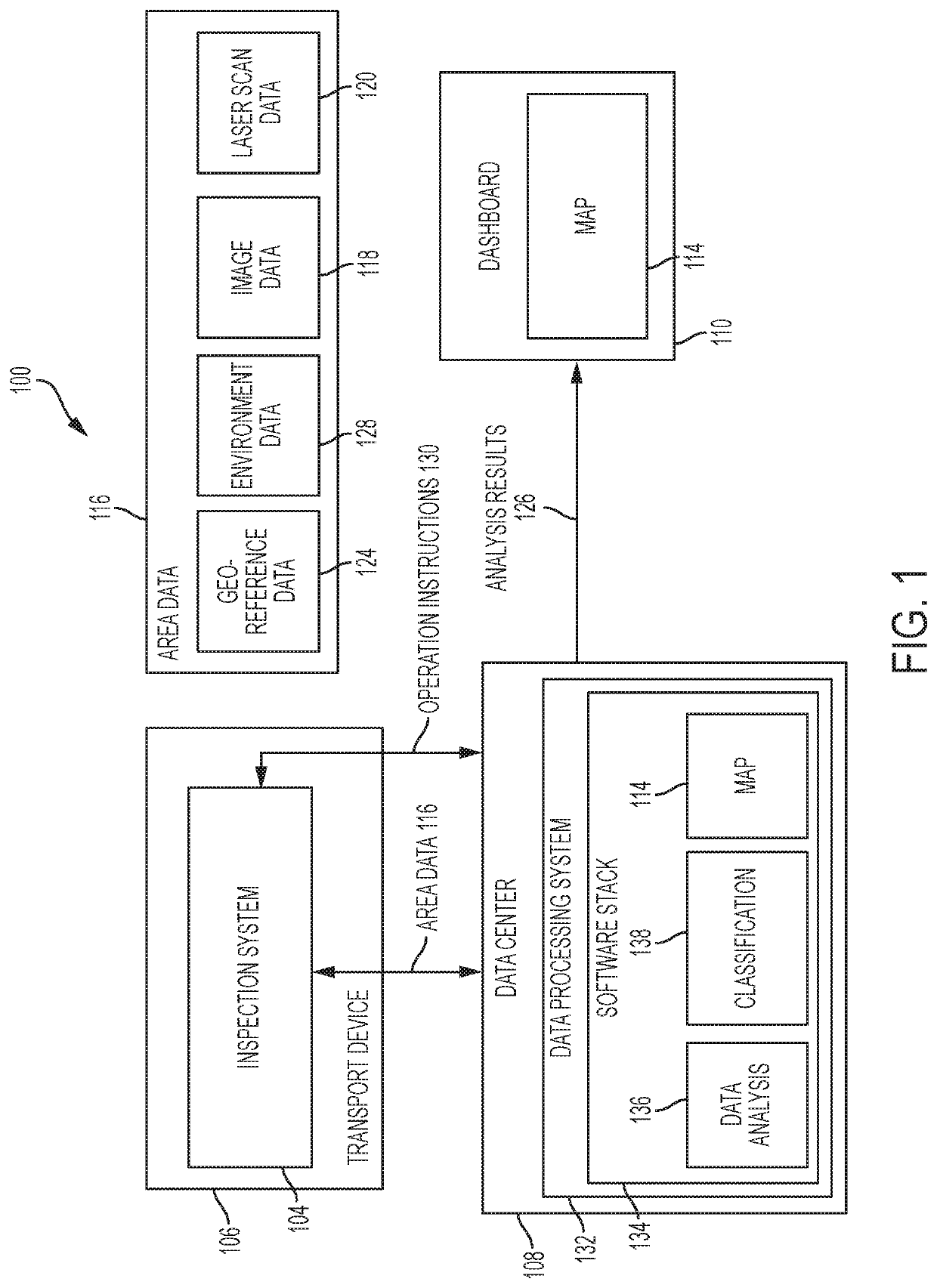
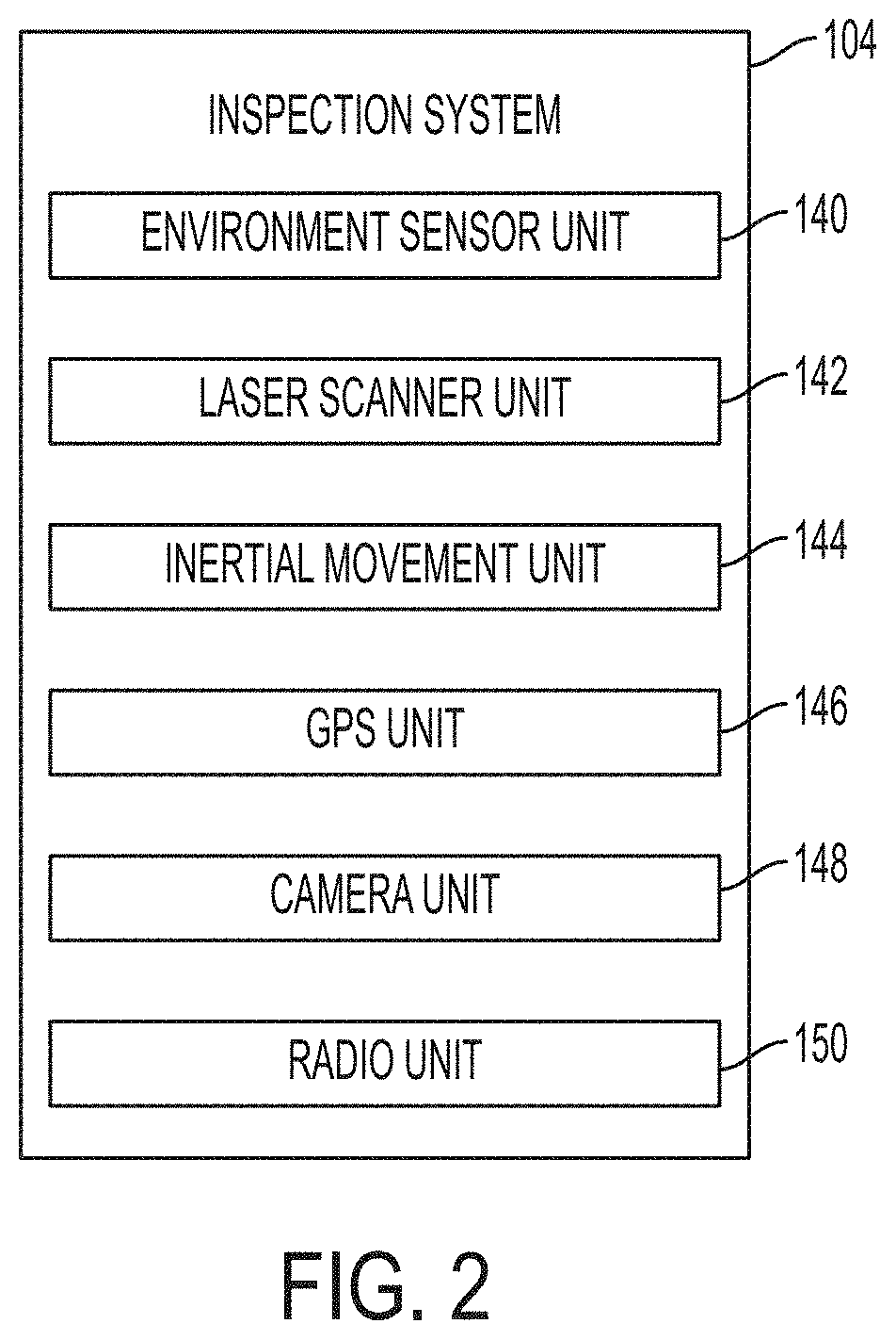
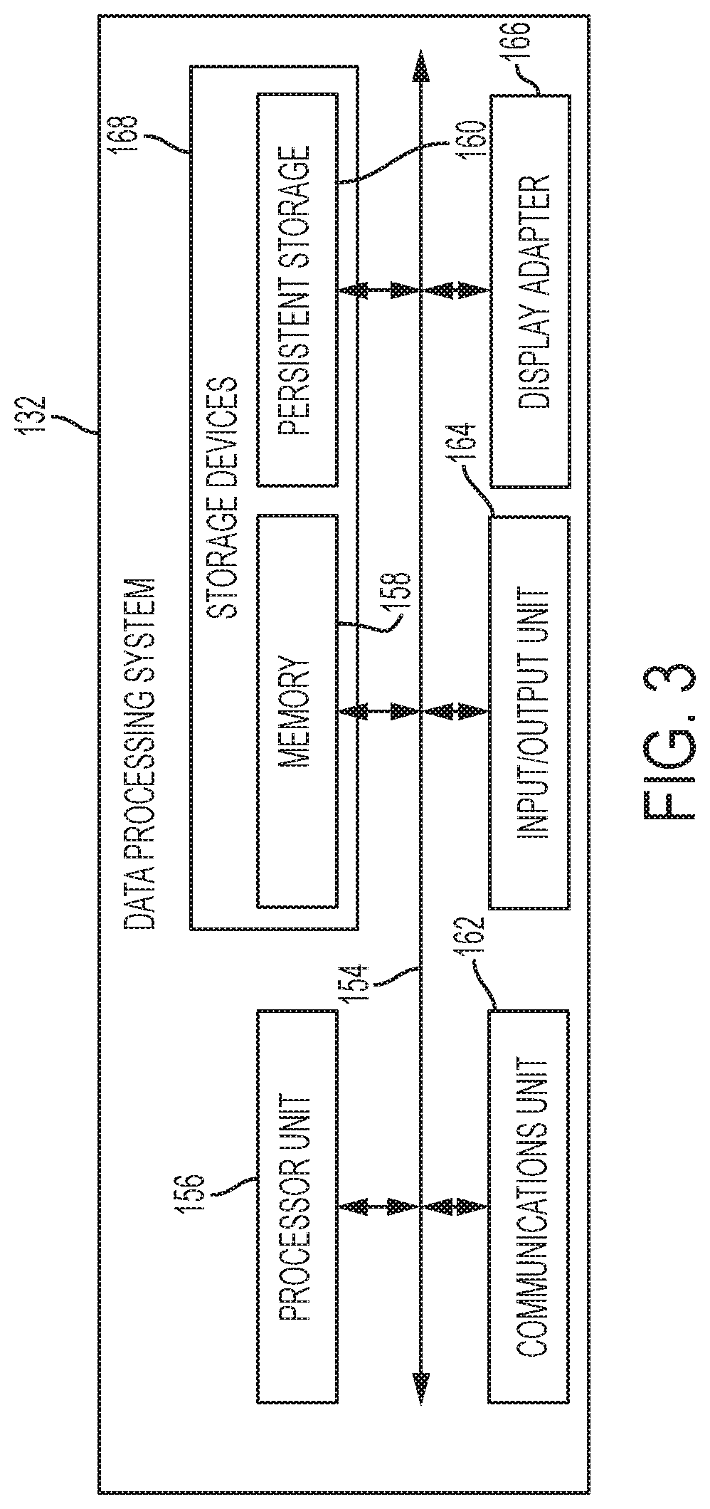
[0021]In the following detailed description, reference is made to the accompanying drawings, which form a part hereof, and in which are shown, by way of illustration, specific examples of embodiments in which the present disclosure may be practiced. These embodiments are described in sufficient detail to enable a person of ordinary skill in the art to practice the present disclosure. However, other embodiments may be utilized, and structural, system, and process changes may be made without departing from the scope of the disclosure. The illustrations presented herein are not meant to be actual views of any particular process, system, device, or structure, but are merely idealized representations that are employed to describe the embodiments of the present disclosure. The drawings presented herein are not necessarily drawn to scale. Similar structures or components in the various drawings may retain the same or similar numbering for the convenience of the reader; however, the similar...


PUM


Abstract

Methods, devices, and systems may be utilized for detecting one or more properties of a plant area and generating a map of the plant area indicating at least one property of the plant area. The system comprises an inspection system associated with a transport device, the inspection system including one or more sensors configured to generate data for a plant area including to: capture at least 3D image data and 2D image data; and generate geolocational data. The datacenter is configured to: receive the 3D image data, 2D image data, and geolocational data from the inspection system; correlate the 3D image data, 2D image data, and geolocational data; and analyze the data for the plant area. A dashboard is configured to display a map with icons corresponding to the proper geolocation and image data with the analysis.

Description

FIELD[0001]The disclosure relates generally to systems and methods for in-field diagnosis of growth stage and crop yield estimation. In particular, the disclosure relates to systems, devices, and methods for in-field diagnosis of the growth stage and crop yield estimation in a plant area and generating a three-dimensional map showing the results.BACKGROUND[0002]Accurate and timely machine counting of fruit on the tree or vine has long been considered impossible or impractical. Conventional methods rely on manual estimation and are often inaccurate and labor intensive. Inaccurate estimates lead to inaccurate crop forecasts and complicate pricing and farmers' ability to forecast and plan.[0003]Accurate crop yield estimation may help farmers improve fruit quality and reduce operating cost by making better decisions on intensity of fruit thinning and size of the harvest labor force. The packing industry may be benefitted as well, because managers can use estimation results to optimize p...

Claims


Application Information

Patent Timeline
IPC IPC(8): G06K9/00G06T7/00G06T7/90G06T17/05G06V10/26
CPCG06T7/90G06T2207/30168G06F3/04817G06T2200/24G06T2207/10024G06T2207/10048G06T2207/10028G06T2207/30188G06T17/05G06T7/0002G06K9/00657A01B79/005G06Q50/02G06V20/64G06V20/188G06V20/38G06V10/993G06V10/26G06V20/17G06V10/803G06F18/251
Inventor GURZONI, JR., JOSE ANGELOAQUINO, JR., PLINIO THOMAZCORTEZ, JR., MILTON PEREZ
Owner ADROIT ROBOTICS
Learn More