Cable with terminal and method of manufacturing the same

a technology of anticorrosion and cable, which is applied in the direction of coupling contact members, connection contact member materials, coupling device connections, etc., can solve the problems of increasing costs, increasing steps, and reducing productivity, so as to prevent electrolytic corrosion of the core wire of the cable. simple and reliably, cost reduction, and improved productivity

Inactive Publication Date: 2020-01-09
YAZAKI CORP
View PDF2 Cites 0 Cited by
  • Summary
  • Abstract
  • Description
  • Claims
  • Application Information

AI Technical Summary

Benefits of technology

[0009]According to the embodiments, the electrolytic corrosion of the core wire of the cable can be prevented simply and reliably by winding the anticorrosion tape material around the crimping portion of the crimp terminal. Therefore, the productivity can be improved and the costs can be reduced.

Problems solved by technology

However, in the conventional cable with a terminal, the heat-shrinkable tube is assembled after the sheet-like member is wound around the sheath crimping portion, so the number of steps is increased and productivity is reduced.
In addition, in the conventional cable with a terminal, the sheet-like member and the heat-shrinkable tube are required, which increases costs.

Method used


Image

  • Cable with terminal and method of manufacturing the same
  • Cable with terminal and method of manufacturing the same
  • Cable with terminal and method of manufacturing the same

Examples


first embodiment

[0033]A first embodiment will be described with reference to FIGS. 1A to 6B.

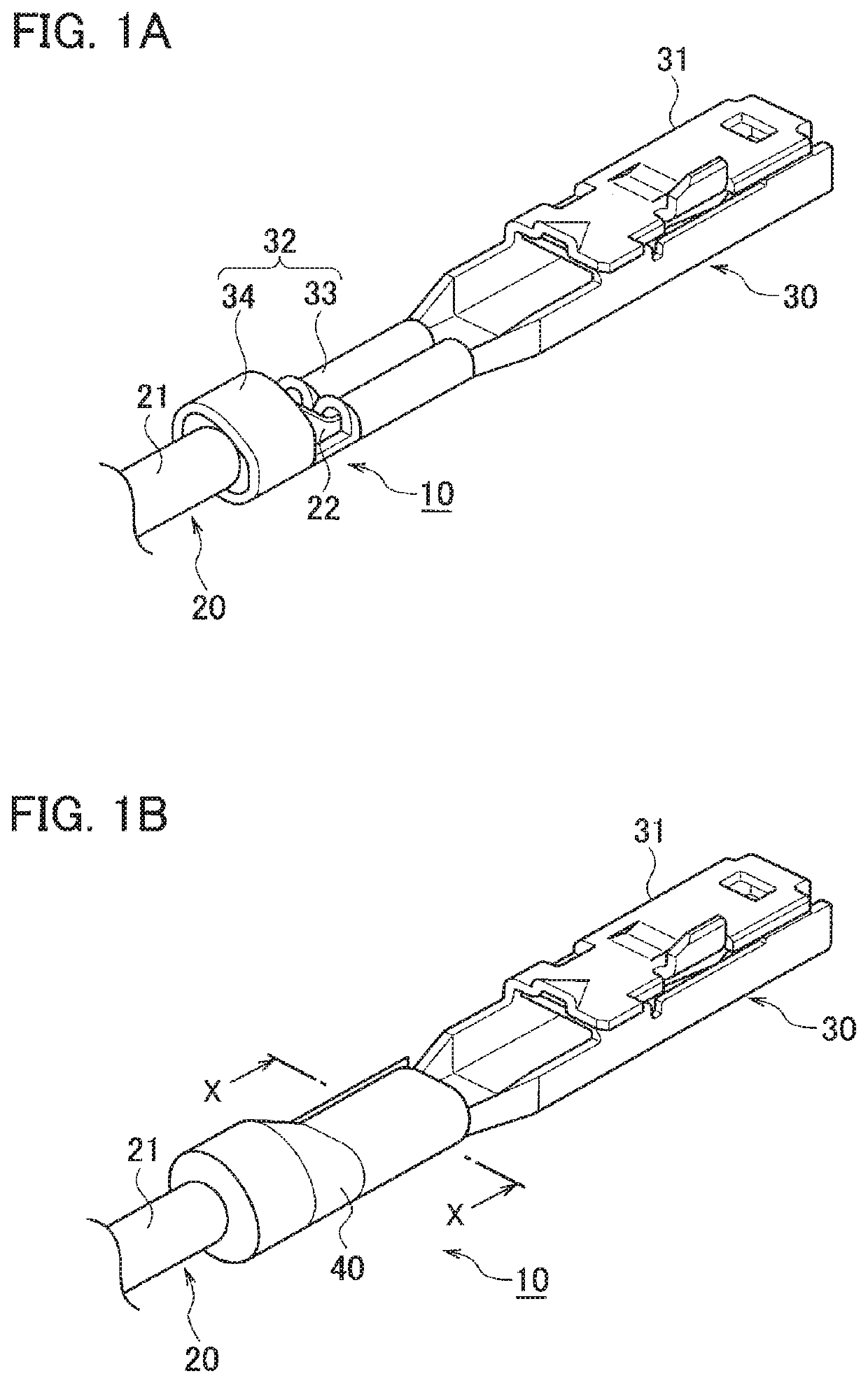
[0034]As illustrated in FIGS. 1A and 1B, a cable 10 with a terminal includes a cable 20 and a crimp terminal 30 made of metal. In the cable 20, a core wire 22 is covered with an insulating sheath 21. The crimp terminal 30 has a box-shaped terminal connection portion 31 and a crimping portion 32.

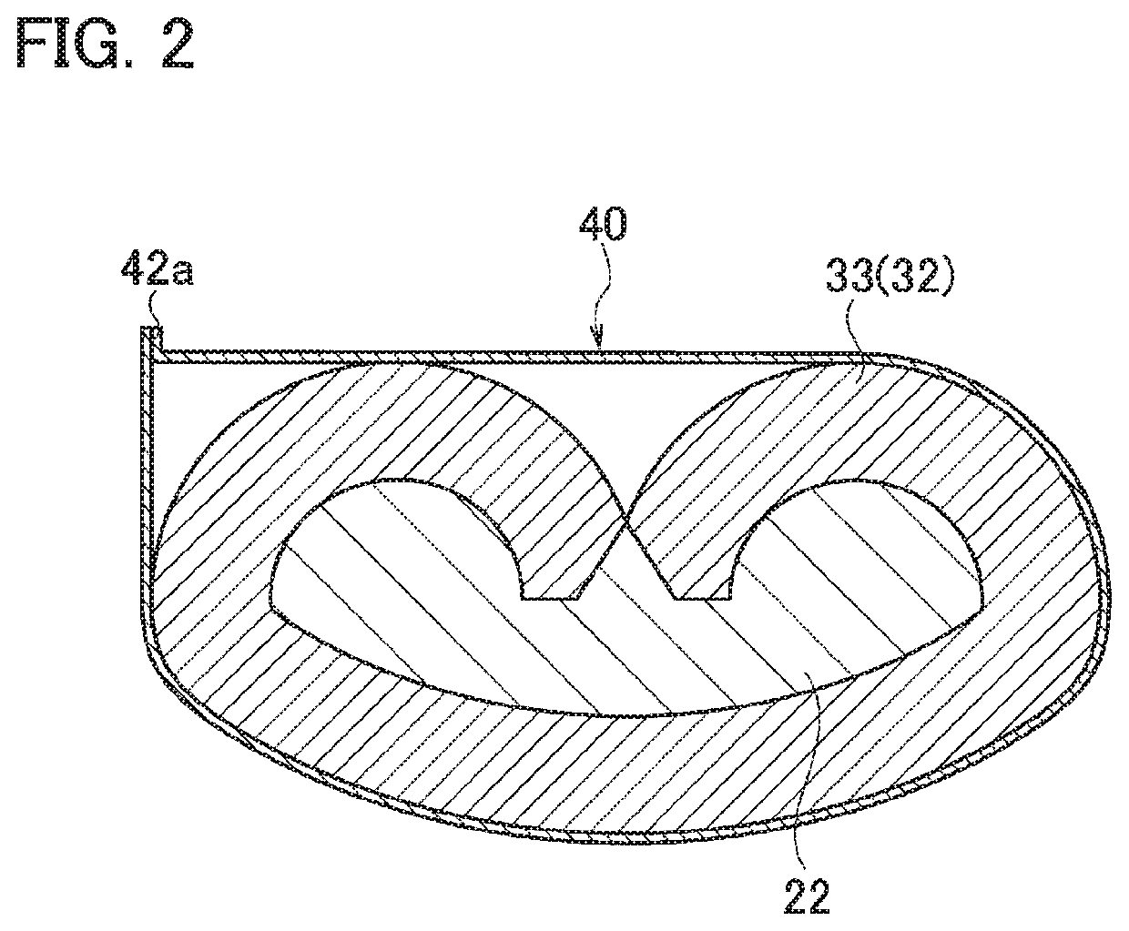
[0035]The terminal connection portion 31 is formed on a front side of the crimp terminal 30. The other terminal is electrically connected to the terminal connection portion 31. The crimping portion 32 has a core wire barrel (core wire crimping portion) 33 and a sheathed barrel (sheath crimping portion) 34. The core wire barrel 33 is crimped to the core wire 22 exposed from the insulating sheath 21 at a rear side from a center of the crimp terminal 30. The sheathed barrel 34 is crimped to the insulating sheath 21.

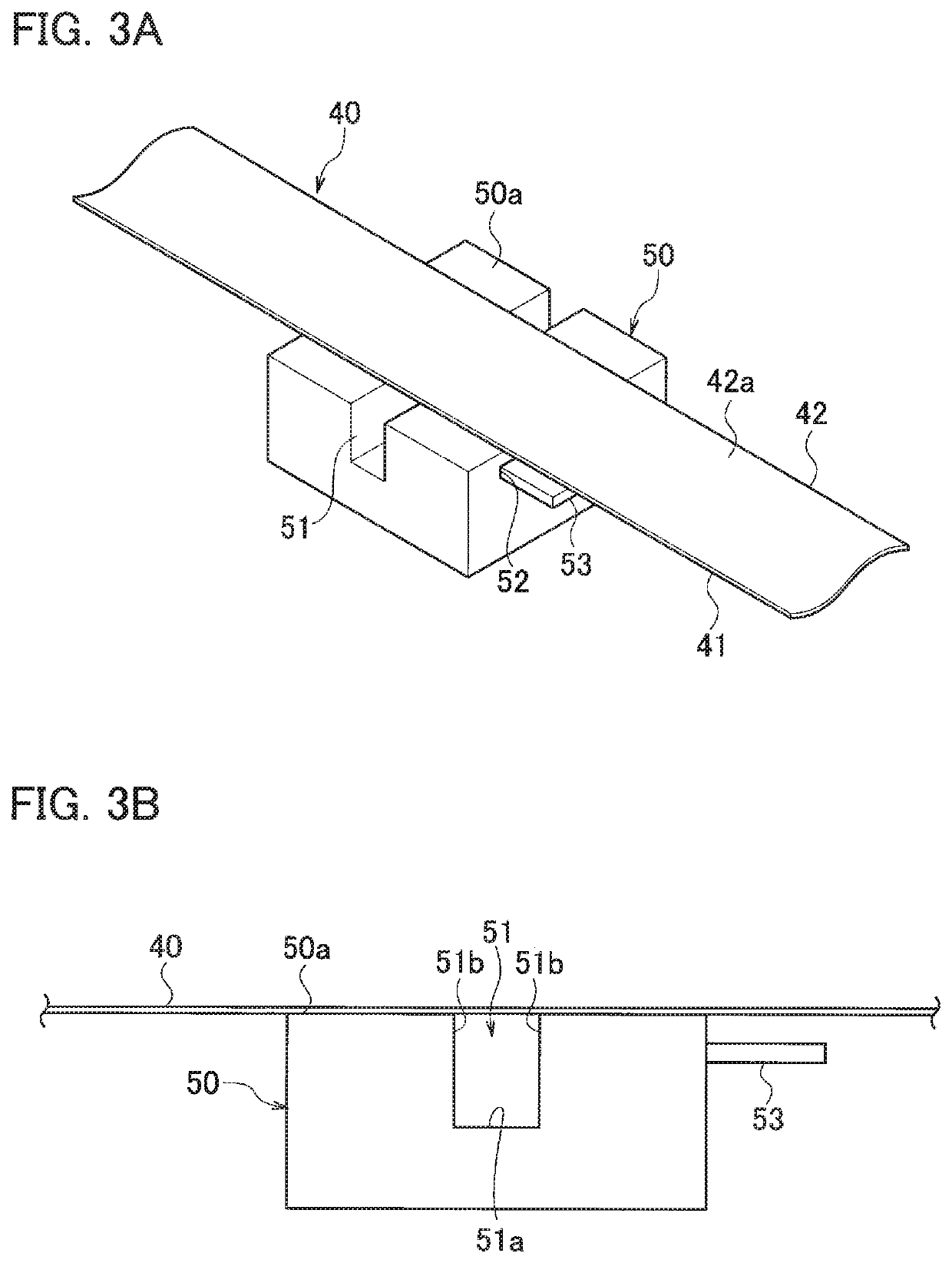
[0036]An anticorrosion tape material 40 is stuck around the crimping portion 32 of the crimp terminal 30.

[0...

second embodiment

[0050]A second embodiment will be described with reference to FIGS. 7A to 11.

[0051]In a cable 10A with a terminal (see FIGS. 7A and 7B), by rotating the crimp terminal 30, the anticorrosion tape material 40 is wound and stuck around the crimping portion 32 including the core wire barrel (core wire crimping portion) 33 and the sheathed barrel (sheath crimping portion) 34. This point is different from the first embodiment. In addition, since other configurations are the same as those of the first embodiment, the same reference numerals are given to the same components and the detailed description is omitted.

[0052]A method of manufacturing a cable 10A with a terminal will be described in order along FIGS. 9 to 11.

[0053]By a caulking die formed of a crimper, an anvil, and the like, the core wire 22 exposed from the insulating sheath 21 of the cable 20 is crimped to the core wire barrel 33 of the crimp terminal 30 beforehand, and the insulating sheath 21 of the cable 20 is crimped and co...


PUM

PropertyMeasurementUnit
adhesiveaaaaaaaaaa
insulatingaaaaaaaaaa
circumferenceaaaaaaaaaa

Abstract

A cable with a terminal includes a cable and a crimp terminal. In the cable, a core wire is covered with an insulating sheath. A crimp terminal has a core wire crimping portion and a sheath crimping portion. The core wire crimping portion is crimped to the core wire exposed from the insulating sheath. The sheath crimping portion is crimped to the insulating sheath. An anticorrosion tape material is stuck around the crimping portion of the crimp terminal.

Description

CROSS REFERENCE TO RELATED APPLICATION[0001]This application is based upon and claims the benefit of priority from the prior Japanese Patent Application No. 2018-128743, filed on Jul. 6, 2018, the entire contents of which are incorporated herein by reference.BACKGROUND1. Technical Field[0002]The present invention relates to a cable with a terminal subjected to anticorrosion treatment and a method of manufacturing the same.2. Related Art[0003]For example, a cable with a terminal subjected to anticorrosion treatment has been disclosed in Patent Literature 1 (JP 2016-110894 A). The cable with a terminal includes a terminal and an aluminum cable. A sheath crimping portion of the terminal is crimped to an insulating sheath of the aluminum cable. The sheath crimping portion is covered with a sheet-like member. A welding portion is a connection portion between the terminal and a core wire exposed from the insulating sheath of the aluminum cable. A circumference of the sheet-like member and...

Claims


Application Information

Patent Timeline
Patent Type & Authority Applications(United States)
IPC IPC(8): H01R4/18H01R13/52H01R4/62H01R13/03H01R43/048
CPCH01R4/62H01R43/048H01R13/5216H01R4/185H01R13/03H01R4/18H01R13/533H01R43/20H01R4/70
Inventor SAITO, HIDEKITAKAHASHI, KAZUHIDESATO, KEI
Owner YAZAKI CORP
Why Eureka
Try Eureka