Chassis dynamometer, control method for the same, and chassis dynamometer program

Active Publication Date: 2020-01-09
HORIBA LTD
View PDF0 Cites 1 Cited by
  • Summary
  • Abstract
  • Description
  • Claims
  • Application Information

AI Technical Summary

Benefits of technology

The present invention provides a chassis dynamometer that can accurately test a two-wheel drive vehicle while reducing the burden on the operator. The configuration of the chassis dynamometer is shown in FIG. 1. Overall, the invention allows for more consistent and reliable testing of vehicles.

Problems solved by technology

Further, larger operating force is exerted on the driven wheel side brakes having higher braking ability to cause serious problems such as not only the overheat but tire damage due to brake lock-up, the impossibility of keeping driven wheel side speed, and the like.

Method used


Image

  • Chassis dynamometer, control method for the same, and chassis dynamometer program

Examples


Embodiment Construction

[0019]In the following, a chassis dynamometer according to one embodiment of the present invention will be described with reference to the drawing.

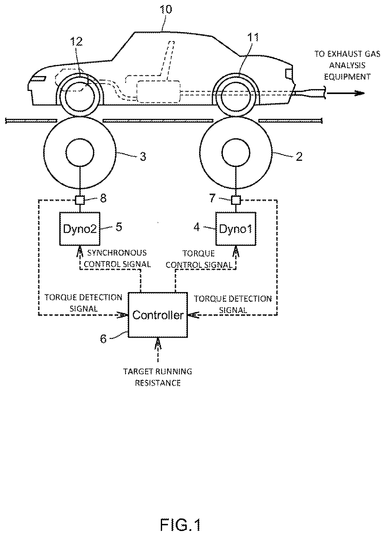
[0020]The chassis dynamometer 100 of the present embodiment is one that simulates an on-road run of a two-wheel drive vehicle 10 to test the vehicle 10, and as illustrated in FIG. 1, includes; a driving wheel side roller 2 on which the driving wheels 11 of the vehicle 10 are placed; a driven wheel side roller 3 on which the driven wheels 12 of the vehicle 10 are placed; a driving wheel side power absorbing part 4 connected to the driving wheel side roller 2; a driven wheel side power absorbing part 5 connected to the driven wheel side roller 3; and a control part 6 that controls the driving wheel side power absorbing part 4 and the driven wheel side power absorbing part 5. Note that FIG. 1 illustrates the case where the rear wheels are the driving wheels 11 and the front wheels are the driven wheels 12, but their relationship may be rever...


PUM


Abstract

A chassis dynamometer that tests a two-wheel drive vehicle includes: a driving wheel side roller on which the driving wheels of the vehicle are placed; a driven wheel side roller on which the driven wheels of the vehicle are placed; a driving wheel side power absorbing part connected to the driving wheel side roller; a driven wheel side power absorbing part connected to the driven wheel side roller; a braking force measuring part that, via the driven wheel side power absorbing part, measures braking force exerted on the driven wheel side roller; and a control part that with use of the braking force measured by the braking force measuring part, sets the control target value of the power absorbing force of the driving wheel side power absorbing part to control the driving wheel side power absorbing part.

Description

TECHNICAL FIELD[0001]The present invention relates to a chassis dynamometer and the like for testing two-wheel drive vehicles.BACKGROUND ART[0002]In recent years, vehicle control technology has been advancing, and a vehicle that senses an unstable running state if all four wheels do not rotate even in the case of a two-wheel drive vehicle and comes into a protective control state has been increasing in number.[0003]When testing such a two-wheel drive vehicle using a chassis dynamometer, as disclosed in Patent Literature 1, not only the driving wheels are placed on the driving wheel side roller, but the driven wheels are also placed on the driven wheel side roller. Then, control is performed so as to exert a load serving as running resistance on the driving wheel side roller, as well as to make the driven wheel side roller follow at the same speed as the rotation speed of the driving wheel side roller.[0004]In a simulated running test using the chassis dynamometer, what decelerate a ...

Claims


Application Information

Patent Timeline
IPC IPC(8): G01M17/007G01M17/02
CPCG01M17/0076G01M17/022G01M17/0074
Inventor NOGUCHI, SHINJIADACHI, KAORI
Owner HORIBA LTD
Why Eureka
Try Eureka