
System and Method for Object Matching Using 3D Imaging

a technology of object matching and 3d imaging, applied in still image data clustering/classification, relational databases, instruments, etc., can solve the problems of difficult identification and repair of specific goods, products, or product lines, and the sheer volume of information is often overwhelming for all, and obtain knowledge that requires years or decades of exposure to lines, etc., to achieve the construction of goods, objects, parts or product databases much more quickly, and the recognition of the effect is much more easily and effectively

Active Publication Date: 2020-01-02
SKUSUB LLC
View PDF0 Cites 4 Cited by
  • Summary
  • Abstract
  • Description
  • Claims
  • Application Information

AI Technical Summary

Benefits of technology

The present recognition system is designed to allow store employees and customers to quickly and automatically identify unknown goods, products, objects, or parts without being familiar with their specific details. It uses 3D scanners, which measure an object's surfaces directly in all three dimensions, allowing for more accurate object recognition. The system can accommodate various user-based scanning methods and has a comprehensive database of profiles for known items. It can quickly provide a ranked list of probable matches even if only a partial scan of the object is available. The use of 3D scanners provides significant advantages in terms of accuracy and efficiency, allowing for faster building of databases and easier recognition of goods, objects, parts, or products.

Problems solved by technology

Almost every industry today shares the common problem of maintaining repair or replacement goods, objects or parts for rapidly expanding product lines.
Over time, the ability to identify and repair specific goods, products, or product lines has become increasingly difficult.
The sheer volume of information is often overwhelming for all but the most expert individuals in a particular field.
Only such experts possess the knowledge and experience necessary to identify these parts, and obtaining that knowledge requires years or decades of exposure to the lines.
Goods, products, or parts identification has thus largely become a lost art, which has led large retailers to only attempt identification, and achieve finding a replacement or matching part for only the most common and readily available items.
Originally plumbing manufacturing was a localized industry, but over time some brands grew to be regional and national, dramatically increasing the number of fixtures in the field and, in turn, the difficulty of parts identification.
As product lines have evolved, many manufacturers have failed to keep track of their own parts for discontinued lines.
Furthermore, in the past two decades, imported products sold through home centers have flooded the market; these fixtures have virtually no manufacturer support in terms of parts identification nor inventory.
Finally, because the plumbing industry has become a fashion industry, entire product lines can change at the whim of fashion trends, compounding the difficulty of parts identification further.
As a result, today there are decades of parts available, but average consumers and distributors have no way of identifying these parts quickly and accurately.
Firstly, the presently available systems capture only a two-dimensional (2D) projection of an object, with no depth information.
The third dimension must be inferred indirectly, for instance by using a very large number of photographs at different angles to train each object type, or is not used at all, severely limiting performance.
In addition to lacking depth, 2D projections also carry no notion of absolute scale, meaning that it is impossible to determine the true physical dimensions of an object solely from images in meaningful real-world units such as inches or millimeters.
Secondly, the appearance of objects in photographs is subject to many external and uncontrolled factors that can dramatically alter measurements from one image to another, and thus makes recognition even more challenging.
Environmental lighting causes reflections and glare, casts shadows, and changes the apparent color and lightness of object surfaces.
The perspective and distance from which an object is viewed, along with geometric lens properties of a camera used in taking the photographs, can distort the object's visible shape, vary its appearance, and cause self-occlusions that differ from image to image.
While exhaustive matching is highly accurate, it can be somewhat slow, and some types of matching may depend on precise object-to-object alignment.
Personnel with the expertise required to identify parts across an entire discipline are increasingly rare, since acquiring this knowledge requires decades of experience.

Method used


Image

  • System and Method for Object Matching Using 3D Imaging
  • System and Method for Object Matching Using 3D Imaging
  • System and Method for Object Matching Using 3D Imaging

Examples


Embodiment Construction

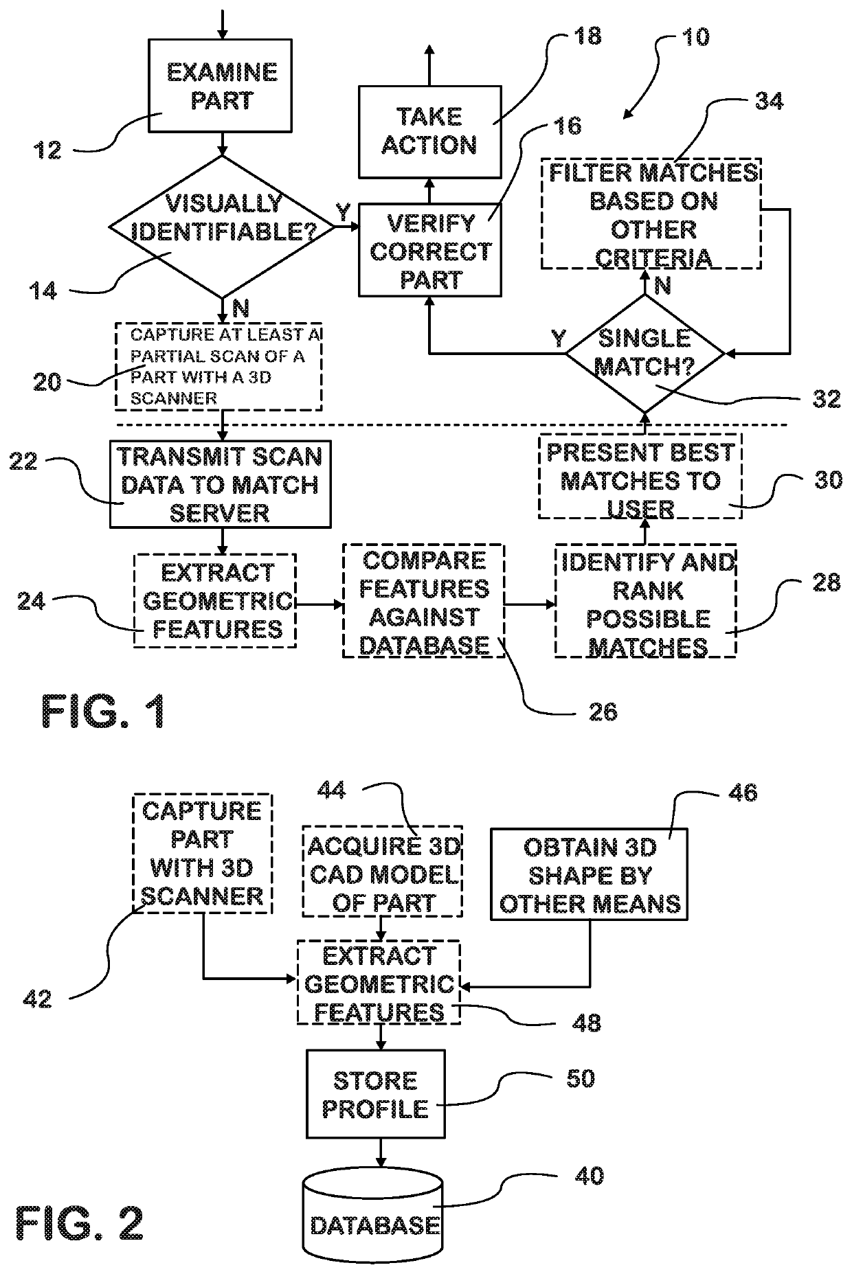
[0043]Turning to FIG. 1, there is illustrated therein a low level system level logic flow 10 diagram wherein a user has a physical good, product, object, or part that he / she wishes to identify, e.g., for the purpose of repair, replacement, matching it to a known part, product, object, or good, finding out the price of the part, or re-ordering. Use of the word “part” in this disclosure also means object, product, or good, and vice versa. Some parts may be easily identified by visual inspection 12 from information imprinted on the surface, prior experience, distinctive shape, size, etc. If such is present, and the part is visually identifiable 14, then one merely verifies that the part is correct in step 16, and takes action, ordering the proper part at 18. However, many are not readily identifiable, perhaps due to uncommon brand, outdated product, damaged / dirty condition, missing information tag, or unfamiliarity. In such a case, the user captures the part parameters with a 3D imagin...


PUM


Abstract

The system and method utilize three-dimensional (3D) scanning technology to create a database of profiles for good, product, object, or part information by producing object representations that permit rapid, highly-accurate object identification, matching, and obtaining information about the object, which is not afforded by traditional two-dimensional (2D) camera imaging. The profiles can compared to a profile of an unknown object to identify, match, or obtain information about the unknown object, and the profiles can be filtered to identify or match the profiles of known objects to identify and / or gather information about an unknown object.

Description

CROSS REFERENCE TO RELATED APPLICATIONS[0001]This application is a continuation-in-part of U.S. Ser. No. 15 / 350,003 filed Nov. 11, 2016, currently pending and titled SYSTEM AND METHOD FOR PART IDENTIFICATION USING 3D IMAGING, which claims priority from U.S. Provisional Patent Application No. 62 / 354,603 filed on Jun. 24, 2016, now expired, of the same title, the content of each is incorporated herein in its entirety by reference, as if fully restated herein.BACKGROUND OF THE INVENTIONField of the Invention[0002]The present invention deals with three-dimensional (3D) scanning technology which produces object representations which permit rapid, highly-accurate object identification and matching of the object to an object in a database which is not afforded by traditional two-dimensional (2D) camera imaging.Prior Art[0003]Selling of objects, products, or goods, such as, but not limited to, clothing, housewares, groceries, and replacement parts is a huge business, and an automated approa...

Claims


Application Information

Patent Timeline
Patent Type & Authority Applications(United States)
IPC IPC(8): G06K9/00G06T17/00G06F16/28G06N3/02
CPCG06F16/284G06K9/00201G06T17/00G06N3/02G06F16/5854G06F16/55G06V20/64G06V20/66
Inventor MEANY, KEITH H.ANTONE, MATTHEW
Owner SKUSUB LLC
Learn More