Periodontal pocket examination apparatus

a pocket examination and pocket technology, applied in the field of pocket examination apparatus, can solve the problems of difficult to ensure the accuracy of measurement, inability to accurately measure, and inability to accurately detect the presence of periodontal disease in the affected parts, so as to improve the operation of the examination probe.

Inactive Publication Date: 2020-01-02
TANITA CORP
View PDF0 Cites 1 Cited by
  • Summary
  • Abstract
  • Description
  • Claims
  • Application Information

AI Technical Summary

Benefits of technology

[0022]In accordance with the present invention, since the measuring light is deflected by the crystal deflecting device, the examination probe can be miniaturized in comparison with a case where the measuring light is deflected using a galvanomirror that requires a driving unit. Further, in the examination probe, the light-emitter that emits the parallelized measuring light from the opening protrudes further along the direction of emission of the measuring light than the gripping portion does. Therefore, in a case where the user such as a dentist inserts the examination probe into the oral cavity of the subject of measurement such as a patient by gripping the gripping portion, the fingers holding the gripping portion can be prevented from contacting the teeth, etc., of the subject, and operability of the examination probe can be improved as well.

Problems solved by technology

However, there are occasions where the result of measurement it not necessarily accurate owing to the extent of the ability of the dentist or the like, the angle of insertion of the pocket probe and visual error, etc.
Further, there is concern that, owing to bleeding from the gums at the time of examination, affected parts free of periodontal disease will become infected with periodontal disease.
The inventors have further recognized that it is difficult to assure accuracy of measurement owing to noise ascribable to vibration or the like produced when the driving system of the galvanomirror is driven.

Method used


Image

  • Periodontal pocket examination apparatus
  • Periodontal pocket examination apparatus
  • Periodontal pocket examination apparatus

Examples


Embodiment Construction

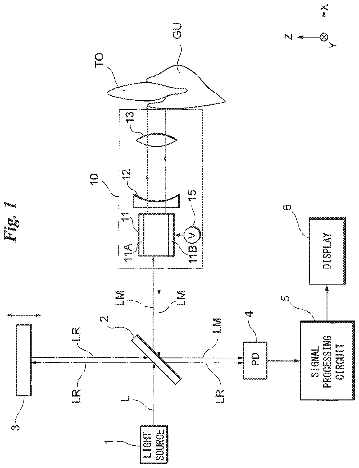
[0038]FIG. 1, which illustrates an embodiment of the present invention, is a block diagram showing the construction of a periodontal pocket examination apparatus.

[0039]Low-interference light (low-coherence light) L is emitted from a light source 1 such as an SLD (Super Luminescent Diode). The low-interference light L is split into measuring light LM and reference light LR by a beam splitter (optical divider) 2. It will suffice if low-interference light L is emitted from the light source 1, and use may be made of another light source such as a gas laser, semiconductor laser or laser diode.

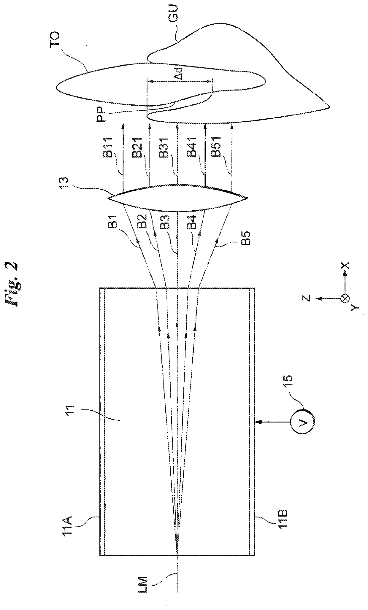
[0040]The measuring light LM split off by the beam splitter 2 impinges upon an examination probe 10. The examination probe 10 includes a crystal deflecting element (a crystal deflecting device) 11, a concave lens 12 and an f-θ lens 13. (Although the f-θ lens corresponds to a parallelizing element, another element will suffice if it is capable of rendering parallel the light emitted from the crystal ...


PUM

PropertyMeasurementUnit
deflection angleaaaaaaaaaa

Abstract

An examination probe used in an apparatus for examining the depth of a periodontal pocket includes a light-emitting portion and a gripping portion. The light-emitting portion includes a crystal deflecting element, which deflects, in a specific direction, measuring light split off from low-interference light, and an f-θ lens for rendering parallel the measuring light that has been deflected. Measuring light that has been rendered parallel such as a measuring light beam is emitted from an opening of the light-emitting portion and irradiates a gum or tooth of a subject. An optical tomographic image of the gum or tooth is generated from interference signals obtained based on reflected light, allowing the depth of a periodontal pocket to be determined. The light-emitting portion protrudes further than the gripping portion does in the direction of emission of the measuring light such as the measuring light beam.

Description

TECHNICAL FIELD[0001]This invention relates to a periodontal pocket examination apparatus.BACKGROUND ART[0002]Measurement of the depth of a periodontal pocket is carried out as one example of an examination of periodontal disease. In general, the depth of a periodontal pocket is measured visually as by a dentist inserting a rod-like measuring instrument referred to as a “pocket probe” into the periodontal pocket. However, there are occasions where the result of measurement it not necessarily accurate owing to the extent of the ability of the dentist or the like, the angle of insertion of the pocket probe and visual error, etc. Further, there is concern that, owing to bleeding from the gums at the time of examination, affected parts free of periodontal disease will become infected with periodontal disease. For these reasons, consideration has been given to the measurement of periodontal pocket depth non-invasively using an optical coherence tomographic diagnostic apparatus (Patent Do...

Claims


Application Information

Patent Timeline
Patent Type & Authority Applications(United States)
IPC IPC(8): A61C19/04A61B1/06A61B1/24A61B1/00G02F1/29G01B9/02
CPCA61C19/043A61B1/06A61B1/24A61B1/00039G01B9/0203A61B1/00096G01B9/0205G02F1/29G01B9/02091A61B1/00177A61B5/0088A61B5/4552A61B5/1079A61B5/0066A61B1/0625
Inventor SHINDO, MIKIO
Owner TANITA CORP
Why Eureka
Try Eureka