Method for making stator of rotary electrical machine

a technology of rotary electrical machines and stators, which is applied in the direction of dynamo-electric machines, dynamo-electric components, magnetic circuit shapes/forms/construction, etc., can solve the problems of affecting occupying more space in the notch, and winding is not well compacted, so as to achieve simple and rapid formation of closure elements, without damaging the wire, and without reducing the performance of the electrical machine

Active Publication Date: 2019-12-26
VALEO EQUIP ELECTRIC MOTEUR
View PDF5 Cites 1 Cited by
  • Summary
  • Abstract
  • Description
  • Claims
  • Application Information

AI Technical Summary

Benefits of technology

[0027]This permits the simple and rapid formation of the closure elements, without damaging the wire, and without reducing the performance of the electrical machine. For example, the closure element can be formed on a stator without a tooth root. It then acts as a tooth root. The notch closure element can also be formed on a stator already provided with tooth roots.
[0052]According to a general characteristic of the invention, the method comprises a step of closure at the notch opening, so that the winding part which is accommodated in the said notch is retained between the notch base and the said closure element, and the closure step comprises a step of offsetting of at least one of the metal sheets of an adjacent notch in the direction of the said notch. For example, the closure step can be carried out on a stator without a tooth root. This therefore makes it possible to form a tooth root. The notch closure step can also be carried out on a stator already provided with tooth roots.

Problems solved by technology

In these machines two problems in particular arise on the winding 5 of the stator body 4.
Firstly, the winding is not well compacted, and occupies more space in the notch than it could occupy if it were compacted.
This is detrimental, since, for a given total length of wire, the addition of copper in the notches makes it possible to increase the performance, and in particular the output of the machine.
Secondly, the winding is not well secured in the notches, and can project from the inner diameter of the stator, which gives rise to a risk of collision with the rotor in rotation.
The solutions proposed according to the prior art do not make it possible to solve this problem satisfactorily.
In this case, the wire, and in particular its insulator, are liable to be damaged during this operation.

Method used


Image

  • Method for making stator of rotary electrical machine
  • Method for making stator of rotary electrical machine
  • Method for making stator of rotary electrical machine

Examples


first embodiment

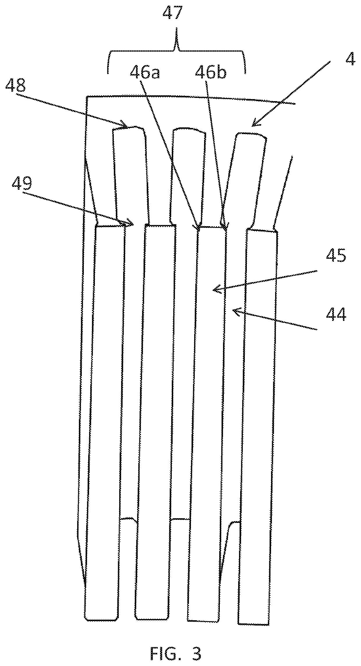
[0082]In the case of the first embodiment, according to one embodiment the tool 60 retains the same axial position relative to the stator. This then provides closure elements 451, 452a, 453 and 454 which are situated on the same radial plane. According to another embodiment, it would be possible to carry out relative axial displacement of the tool 60 in relation to the stator 4. This relative axial displacement is carried out for example at the same time as the relative rotation of the stator 4 in relation to the tool 60. This then means that the closure elements 451, 452a are situated on a first radial plane, and the closure elements 453 and 454 are situated on a second radial plane, these first and second radial planes being different. For example, the first and second radial planes are situated at a distance greater than two metal sheets.

second embodiment

[0083]In the second embodiment, the tool 60 in FIG. 7 and the one in FIG. 8 can be situated on first and second substantially different radial planes. For example, the first radial plane and the second radial plane are spaced axially by a distance equal to at least two metal sheets. This then means that the closure elements 451, 452a are situated on the first radial plane, and the closure elements 453 and 454 are situated on the second radial plane, these first and second radial planes being different.

[0084]It will be appreciated that, as already stated for FIG. 7, N tools 60 could also be provided, distributed axially on the notch 42. They would then give rise to the formation of 2 N closure elements distributed axially. There would also be better compacting of the winding part 52 of the notch 42, thanks to the radial supports distributed axially. For this purpose, it is possible to provide a single tool of the said. N tools 60, in order to facilitate their manipulation.

[0085]FIG. ...

embodiment 1

[0098] the tool for the notches 41, 42 and 43 is identical. According to an example of this embodiment, if only one relative rotation of the stator takes place in relation to the tool, there are then the closure elements 451, 452a, 453, 454, 455 and 452b which are situated on the same radial plane. There is then in particular a single closure element 452 formed. by the two elements 452a and 452b.


PUM


Abstract

A stator of a rotary electrical machine has a stator body formed by a stack of metal sheets. The stator body is delimited by inner and outer radial surfaces. Notches in the stator body extend axially. Each notch has a notch base and a notch opening, and the notch opening is on the side of the inner radial surface. A stator winding is supported by the stator body, and the winding has a plurality of winding parts. Each part is accommodated in one of the notches. Each of the notches at the notch opening has a closure element. Each winding par in a notch is retained between the notch base and the closure element. The closure elements are formed by offsetting at least one of the metal sheets of an adjacent notch in the direction of the notch.

Description

CROSS-REFERENCE TO RELATED APPLICATIONS AND CLAIM TO PRIORITY[0001]This application is related to Patent Application No. 1560709 filed Nov. 9, 2015 in France, the disclosure of which is incorporated herein by reference and to which priority is claimed. This application is a divisional of U.S. application Ser. No. 15 / 347,021, filed Nov. 9, 2016, the entire disclosure of which is incorporated herein by reference and to which priority is claimed.FIELD OF THE INVENTION[0002]The present invention relates to a rotary electrical machine, and more particularly to the stator of a rotary electrical machine of this type.BACKGROUND OF THE INVENTION[0003]Use of rotary electrical machines in motor vehicles is known. These can consist of a compact polyphase alternator. This alternator transforms mechanical energy into electrical energy, and can be reversible. A reversible alternator of this type is known as an alternator-starter, and in another functioning mode transforms electrical energy into me...

Claims


Application Information

Patent Timeline
Patent Type & Authority Applications(United States)
IPC IPC(8): H02K1/16H02K3/487H02K15/00
CPCH02K3/487H02K15/0031H02K1/165H02K2213/03H02K3/48H02K15/0018H02K1/12H02K3/521
Inventor BILTERYST, PIERRE-YVESDELIANNE, HENRIMARGUERITTE, DAVIDJOZEFOWIEZ, ERICPERREAUT, SYLVAINBALTHAZE, PATRICEBATTUT, JULIEN
Owner VALEO EQUIP ELECTRIC MOTEUR
Why Eureka
Try Eureka