
Optical illusion device

Inactive Publication Date: 2019-12-26
CHINA IND
View PDF0 Cites 1 Cited by
  • Summary
  • Abstract
  • Description
  • Claims
  • Application Information

AI Technical Summary

Benefits of technology

The present invention provides an improved optical illusion device that enhances image sharpness and realness, making it more enjoyable to watch. Additionally, the device is more efficient and economical to produce than existing devices, making it suitable for commercial manufacturing. The method may also involve adding detail to the digital sculpt, such as creating embossed and debossed areas, enhancing the original image, and adding tonal balancing, shadow depth, highlights, and reflections to the digital sculpt to maximize the final product.

Problems solved by technology

In general, the two-dimensional reproductions are insufficient in reproducing three-dimensional presence having a large field of view; visual cues such as depth, shading and perspective have historically been impossible to reproduce in two dimensions to create a three-dimensional illusion other than for a discrete viewing point.
Such features however lose the appearance of being three-dimensional since they are not formed on a negative image-forming relief surface.
Although the devices disclosed within U.S. Pat. No. 8,562,182 result in the perception of a three-dimensional image which is enhanced when compared with those disclosed within U.S. Pat. Nos. 2,334,750 and 5,407,391 the devices and associated manufacturing process are highly complex and thus expensive for use within a commercial manufacturing process.

Method used


Image

  • Optical illusion device
  • Optical illusion device
  • Optical illusion device

Examples


Embodiment Construction

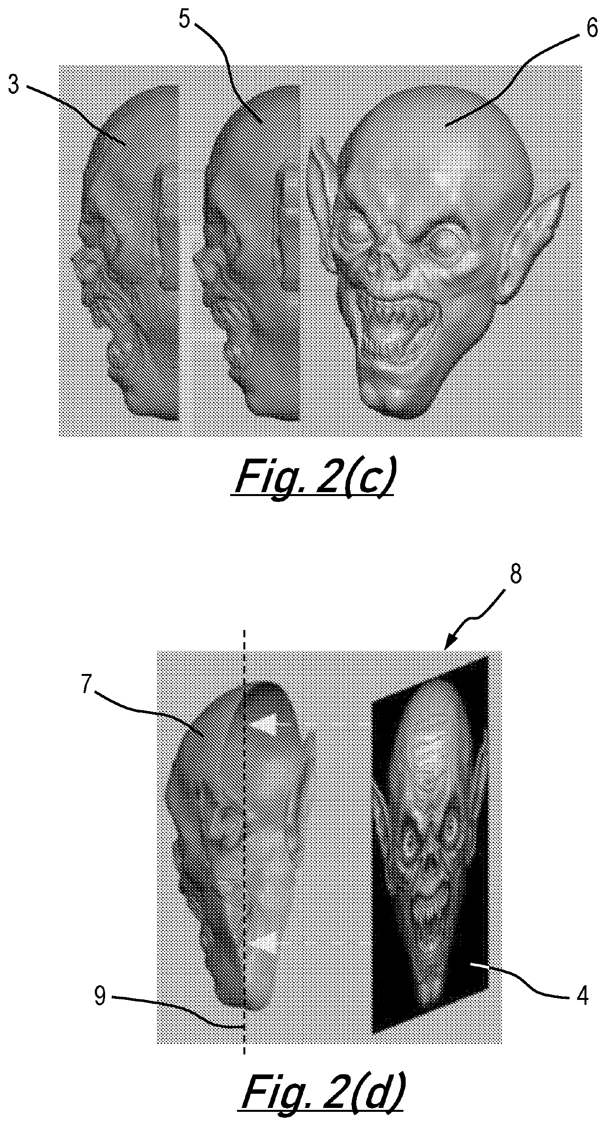
[0047]A method of producing an optical illusion device, as depicted generally be reference numeral 1, will now be described with reference to FIGS. 1 and 2. In particular, FIG. 1 presents a flow chart of a method of production of the optical illusion device 1 while FIG. 2 presents images of the optical illusion device 1 at various stages of its production.

[0048]The first stage of the method presented with FIGS. 1 and 2 involves the creation of a digital sculpt 2 which is to be the subject of the optical illusion (S1001). The digital sculpt 2 may be generated from a two-dimensional image or by creating an original sculpt. If a two-dimensional image is employed to produce the digital sculpt 2 then it is preferable for the digital sculpt 2 to be made to match the parameters of the two-dimensional image when viewed from a substantially perpendicular viewing angle. In the presently described example the digital sculpt 2 is a representation of the face of a goblin, although the head of an...


PUM

PropertyMeasurementUnit
Diameteraaaaaaaaaa
Diameteraaaaaaaaaa
Diameteraaaaaaaaaa

Abstract

An optical illusion device and method of production is described. The method comprises producing a digital sculpt. A rendered visual image and a thinned digital sculpt are then produced from the digital sculpt. Next a digital thickness shell is produced from the thinned digital sculpt. Finally, the rendered visual image is employed to impart a lithophane depth map onto the digital thickness shell. The overall result is an optical illusion device comprising a negative image forming surface with a registered lithophane image imparted on thereon. When the optical illusion device is viewed from various angles (and with a light source placed behind it), the negative image forming surface appears to the viewer as a positive or convex model with a photographic image applied to the profiled surface. The illusion created is of a ‘panning’, three-dimensional photographic image, complete with improved detail due to the presence of the lithophane depth map.

Description

The present invention relates to the field of optical illusion devices and in particular to an optical illusion device based on a negative bust illusion device and a method of producing the same.BACKGROUND TO THE INVENTION[0001]Since the times of early artists, people have endeavoured to create realistic likenesses of themselves, others, and other three-dimensional objects, to thereby impart a sense of presence. Such artistic reproductions have generally taken two dimensional forms, for example, paintings, and also three-dimensional forms, including various types of sculptures. In general, the two-dimensional reproductions are insufficient in reproducing three-dimensional presence having a large field of view; visual cues such as depth, shading and perspective have historically been impossible to reproduce in two dimensions to create a three-dimensional illusion other than for a discrete viewing point.[0002]Sculptures, on the other hand, have proved generally better at visually imit...

Claims


Application Information

Patent Timeline
IPC IPC(8): B44F1/00B44C3/06B44F7/00B29C45/00B29C64/386B33Y50/00B33Y80/00B33Y10/00G06T15/50
CPCB44C3/06B33Y80/00B29K2105/0032B29K2505/02B33Y10/00B29C64/386B44F7/00B29K2995/0025B29C45/0001G06T15/50B44F1/00B33Y50/00B44C1/22B44F1/06G09F19/12
Inventor TAYLOR, GRAEME JOHNWYATT, JAMES EDWARD ALEXANDERGASSON, MARK NEIL
Owner CHINA IND
Learn More