Drive apparatus and display panel

a technology of drive apparatus and display panel, which is applied in the direction of instruments, static indicating devices, etc., can solve the problems of poor frequent charge holding time of liquid crystal cells without being able to make timely responses, and achieve the effect of improving the liquid crystal dynamic capacitance

Inactive Publication Date: 2019-12-19
HKC CORP LTD +1
View PDF11 Cites 0 Cited by
  • Summary
  • Abstract
  • Description
  • Claims
  • Application Information

AI Technical Summary

Benefits of technology

[0017]According to this application, a charging time of a liquid crystal capacitor may be adjusted while maintaining the original manufacturing process requirement and product costs without greatly changing the precondition of the existing production flow, to reduce cases where liquid crystal cells fail to make a timely response, so that the voltage value and the capacitance value of each pixel liquid crystal capacitor of the display panel reach expected values as far as possible, thereby improving the liquid crystal dynamic capacitance effect.

Problems solved by technology

However, within an opening time of a scanning line, the liquid crystal cells frequently enter a charge holding time without being capable of making a timely response.
Consequently, the rotation of the liquid crystal cells is insufficient, and expected voltage value and capacitance value cannot be reached, leading to a relatively poor liquid crystal dynamic capacitance effect.

Method used


Image

  • Drive apparatus and display panel
  • Drive apparatus and display panel
  • Drive apparatus and display panel

Examples


Embodiment Construction

[0026]The following embodiments are described with reference to the accompanying drawings, used to exemplify specific embodiments for implementation of this application. Terms about directions mentioned in this application, such as “on”, “below”, “front”, “back”, “left”, “right”, “in”, “out”, and “side surface” merely refer to directions in the accompanying drawings. Therefore, the used terms about directions are used to describe and understand this application, and are not intended to limit this application.

[0027]The accompanying drawings and the description are considered to be essentially exemplary, rather than limitative. In the figures, modules with similar structures are represented by using the same reference number. In addition, for understanding and ease of description, the size and the thickness of each component shown in the accompanying drawings are arbitrarily shown, but this application is not limited thereto.

[0028]In the accompanying drawings, for clarity, thicknesses...


PUM


Abstract

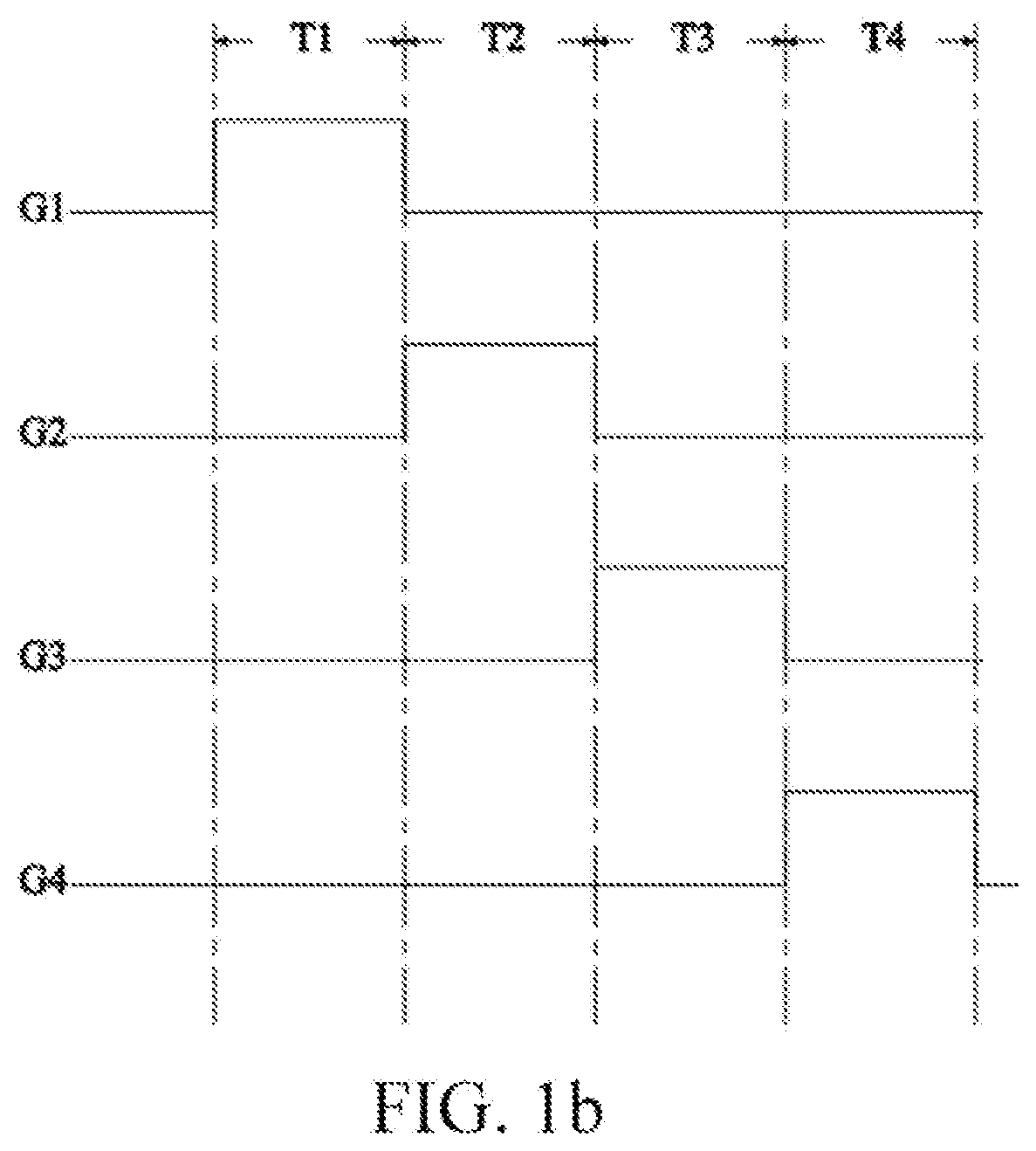
This application provides a drive apparatus and a display panel. The drive apparatus includes: a plurality of gate line groups, where each of the gate line groups includes a plurality of gate lines; and a gate drive unit, connected to the plurality of gate line groups, and configured to input a gate drive signal in each scanning period, where in a scanning period, the gate drive unit alternately provides a scanning signal to the plurality of gate lines.

Description

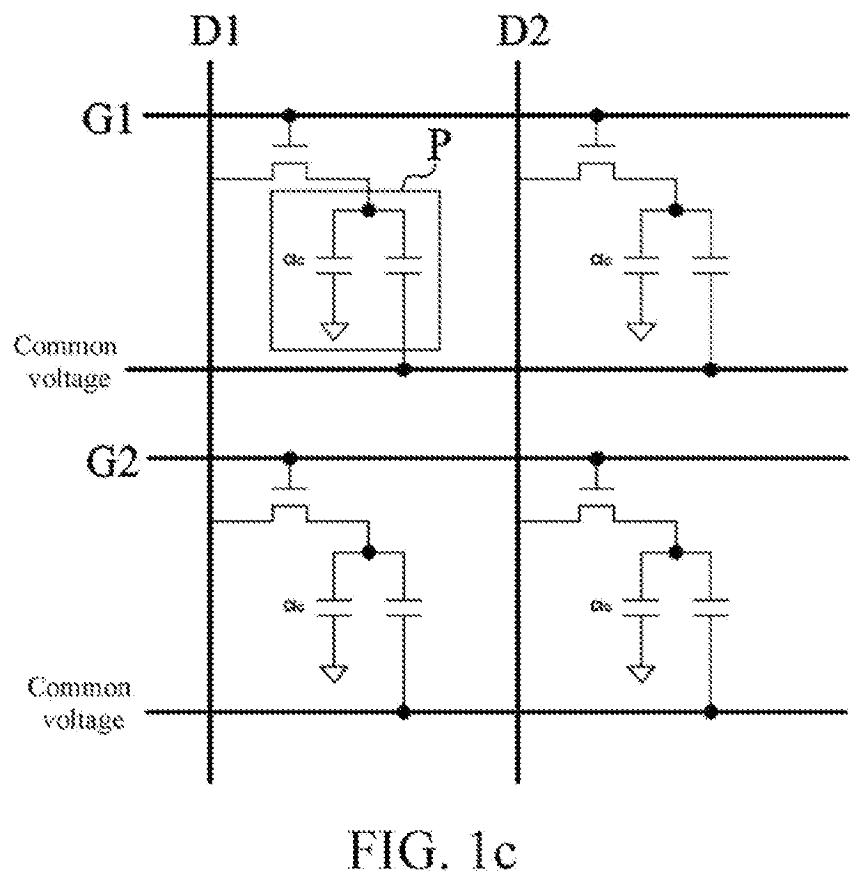
BACKGROUNDTechnical Field[0001]This application relates to the field of display technologies, and in particular, to a drive apparatus and a drive method thereof, and a display panel.Related Art[0002]During normal display of an active switch-liquid crystal display (TFT-LCD) panel, a gate drive line (Gate Driver) combined with a gate line, a source drive line (Source) combined with a data line, and a common electrode (color filter common electrode, CF com) and a storage electrode that are provided for a color filer substrate are required. A signal of a pixel electrode is supplied by the data line after the data line is opened by using the active switch (TFT). A signal of the storage electrode is supplied by an array common line (AA Com) on a periphery of an effective display region, to form a storage capacitance (Cst) between the storage electrode and the pixel electrode. A signal of the color filter common electrode is supplied by a common voltage line of a wire on array (WOA) of an ...

Claims


Application Information

Patent Timeline
Patent Type & Authority Applications(United States)
IPC IPC(8): G09G3/36
CPCG09G2310/08G09G2310/0281G09G3/3677G09G2310/0202G09G3/3688G09G3/3648G09G2300/0426G09G2230/00G09G3/3266
Inventor LI, WENXIN
Owner HKC CORP LTD
Why Eureka
Try Eureka