
Server rail and server rack mounting structure

a technology for server rails and racks, applied in the field of server technology, can solve the problems of increasing installation costs, requiring much labor and time, etc., and achieve the effect of convenient installation

Active Publication Date: 2019-12-05
GSLIDE
View PDF1 Cites 4 Cited by
  • Summary
  • Abstract
  • Description
  • Claims
  • Application Information

AI Technical Summary

Benefits of technology

The present invention provides a server rail and server rack mounting structure that allows for easy installation without tools. The mounting bracket and swivel control member securely attach the server rail to the server rack using an abutment wall and stop wall, ensuring stability during installation. The structure uses a minimal number of parts, making installation easier. The technical effects of this invention are improved ease of installation, enhanced stability, and simplified parts usage.

Problems solved by technology

In installation, it requires much labor and time, increasing the installation cost.

Method used


Image

  • Server rail and server rack mounting structure
  • Server rail and server rack mounting structure
  • Server rail and server rack mounting structure

Examples


Embodiment Construction

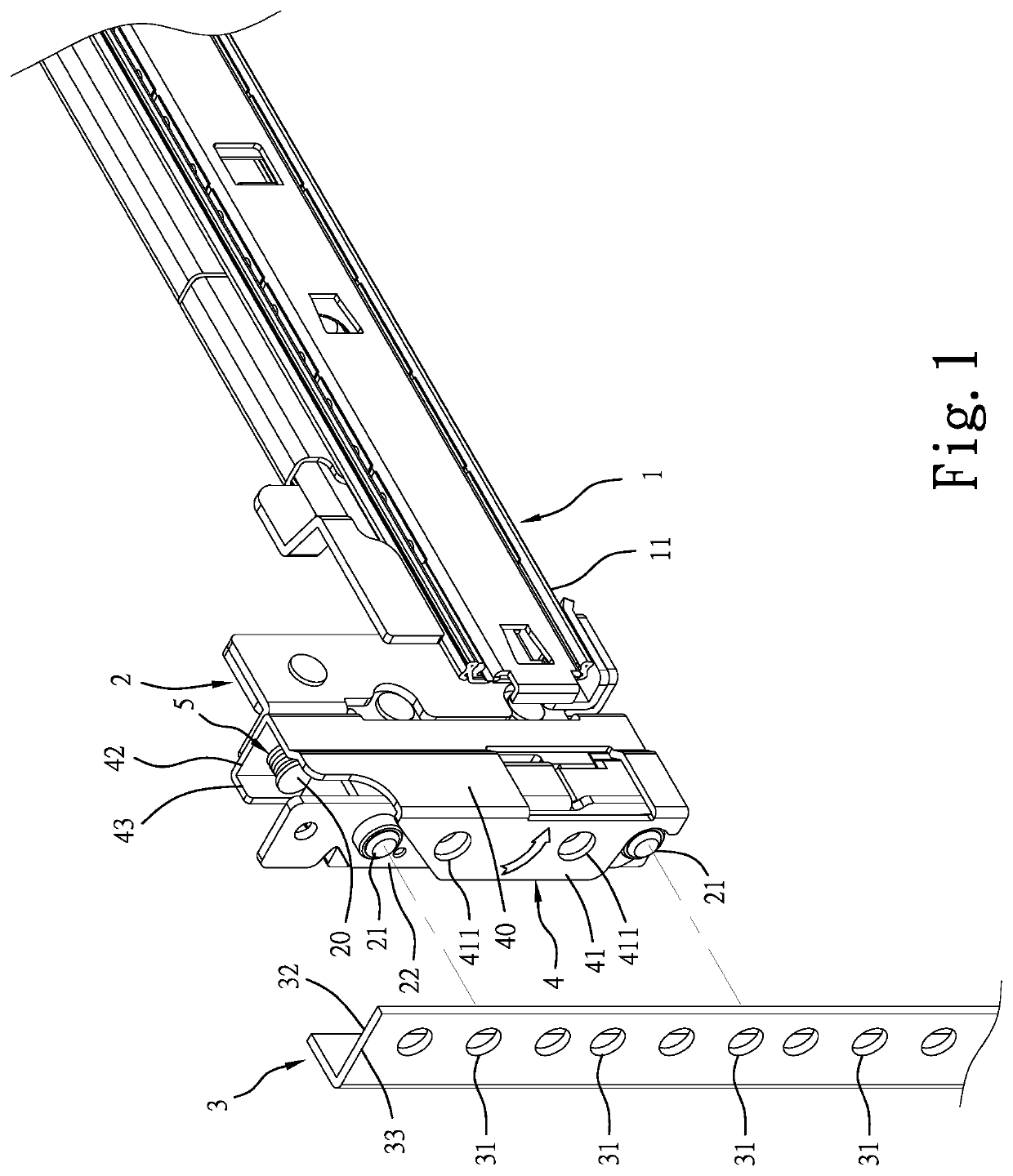
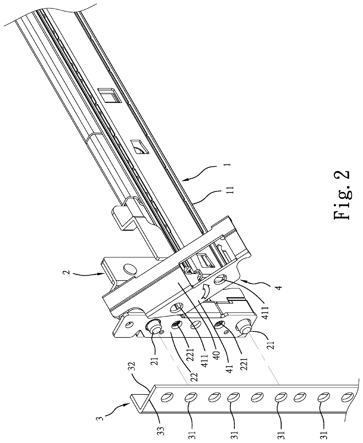
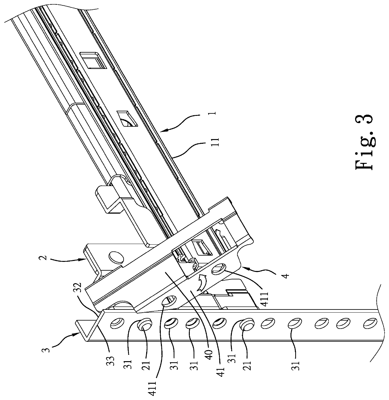
[0016]Referring to FIGS. 1-7, a server rail and server rack mounting structure comprises a server rail 1, a server rack 3 having a plurality of locating holes 31 at one side thereof, and a mounting bracket 2 located at one end of an outer rail portion 11 of the server rail 1 and comprising a plurality of mounting rods 21 that are configured to be respectively plugged into respective locating holes 31 of the server rack 3, and an abutment wall 22 neighbored or adjacent to the mounting rods 21.

[0017]The main features of the server rail 1 and server rack mounting structure include a swivel control member 4, a pivot member 20 pivotally connect one end of the swivel control member 4 to the mounting bracket 2, and a torsion spring 5 mounted around the pivot member 20 with one end 51 stopped against the mounting bracket 2 and an opposite end 52 thereof stopped against the swivel control member 4 (FIGS. 1 and 4-6). Further, the swivel control member 4 comprises a stop wall 41.

[0018]When usi...


PUM


Abstract

A server rail and server rack mounting structure includes a server rail, a server rack having a plurality of locating holes, a mounting bracket located at one end of an outer rail portion of the server rail and having a plurality of mounting rods respectively plugged into respective locating holes of the server rack and an abutment wall neighbored to the mounting rods, a swivel control member comprising a stop wall, a pivot member pivotally connect one end of the swivel control member to the mounting bracket and a torsion spring mounted around the pivot member and stopped between the mounting bracket and the swivel control member.

Description

FIELD OF THE INVENTION[0001]The present invention relates to server technology and, more particularly, to a server rail and server rack mounting structure.BACKGROUND OF THE INVENTION[0002]Taiwan Patent Number 1624235, issued to the present inventor, discloses a server rail front bracket quick release structure for quick connection of the outer rail of the server rail to the server rack. This design of server rail front bracket quick release structure uses a large number of component parts such as front bracket, connection block, swivel hook, pivot member, retainer, lever, outer socket, inner lock pin, springs, and etc. In installation, it requires much labor and time, increasing the installation cost.[0003]Other designs for mounting a server rail to a server rack are seen in Taiwan Patent Number 1608780 entitled “Server and modem rack mounting structure (III)”; Taiwan Patent Number 1573518 entitled “Server rail bracket assembly”; Taiwan Patent Number 1427756 entitled “Server and mod...

Claims


Application Information

Patent Timeline
Patent Type & Authority Applications(United States)
IPC IPC(8): H05K7/18A47B88/43A47B88/483
CPCH05K7/183A47B88/483A47B88/43A47B2210/0002H05K7/1489
Inventor CHEN, YUNG-LIANG
Owner GSLIDE
Learn More