
Fire-rated joint component and wall assembly

a technology components, which is applied in the direction of walls, building components, construction, etc., can solve the problems of noise, smoke or heat passing through the deflection gap, and the conventional construction of fire-rated head-of-wall joints is time-consuming, and achieves the effect of improving the seal and improving the sealing seal

Active Publication Date: 2019-11-28
CEMCO LLC
View PDF253 Cites 16 Cited by
  • Summary
  • Abstract
  • Description
  • Claims
  • Application Information

AI Technical Summary

Benefits of technology

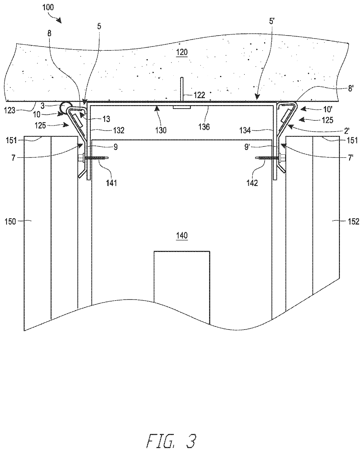
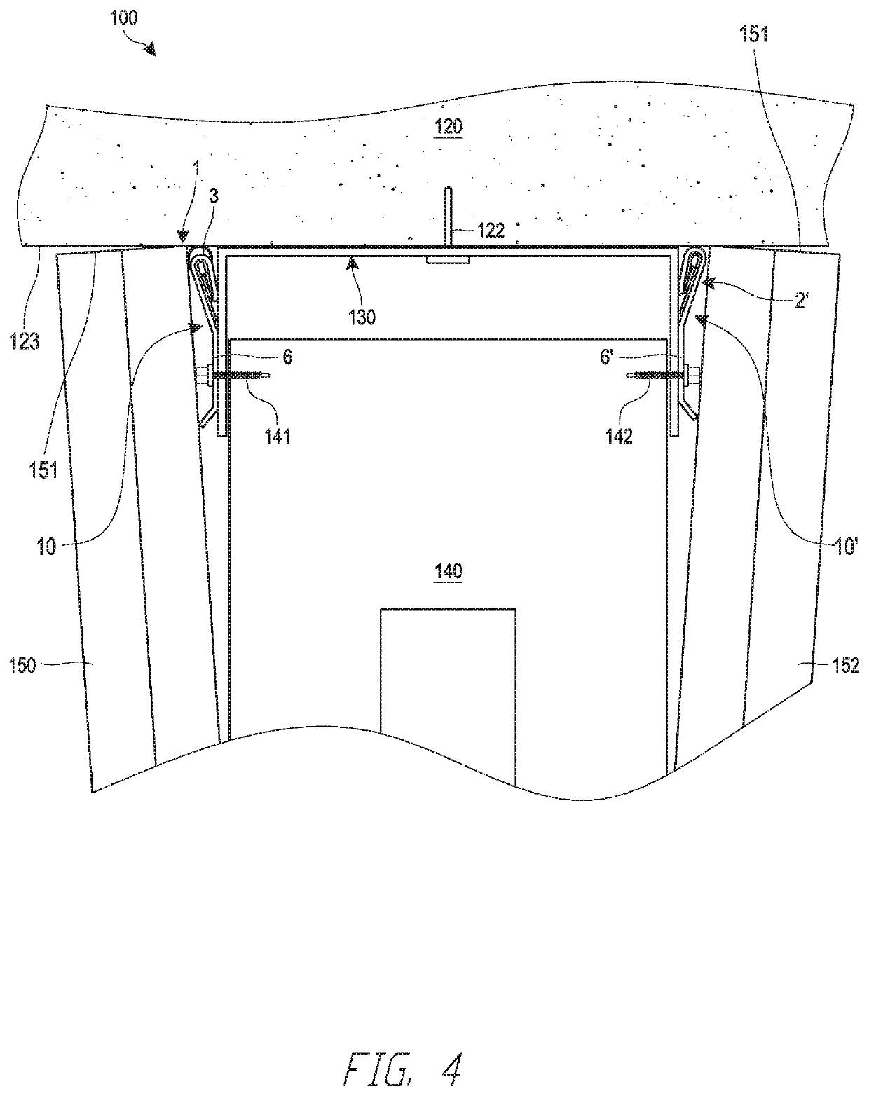
The patent text describes a head-of-wall assembly that provides a better seal to prevent the passage of noise, smoke, and heat between adjacent rooms. This is achieved by using an improved fire-blocking gasket that is designed to create a tight seal. Additionally, the foam tape used in the assembly helps to create space between the header track and the wallboard to allow for movement of the fastener head due to cycling movement between the ceiling and the studs. Overall, the technical effects of this patent are improved prevention of noise, smoke, and heat passage and improved movement of fasteners.

Problems solved by technology

This conventional construction of a fire-rated head-of-wall joint is time-consuming, expensive and has other disadvantages.
If the wall studs are rigidly attached to the slotted track and not allowed to move freely in at least one direction, the stability of the wall and the building might be compromised.
In some head-of-wall assemblies, the noise, smoke or heat can pass through the deflection gap.

Method used


Image

  • Fire-rated joint component and wall assembly
  • Fire-rated joint component and wall assembly
  • Fire-rated joint component and wall assembly

Examples


second embodiment

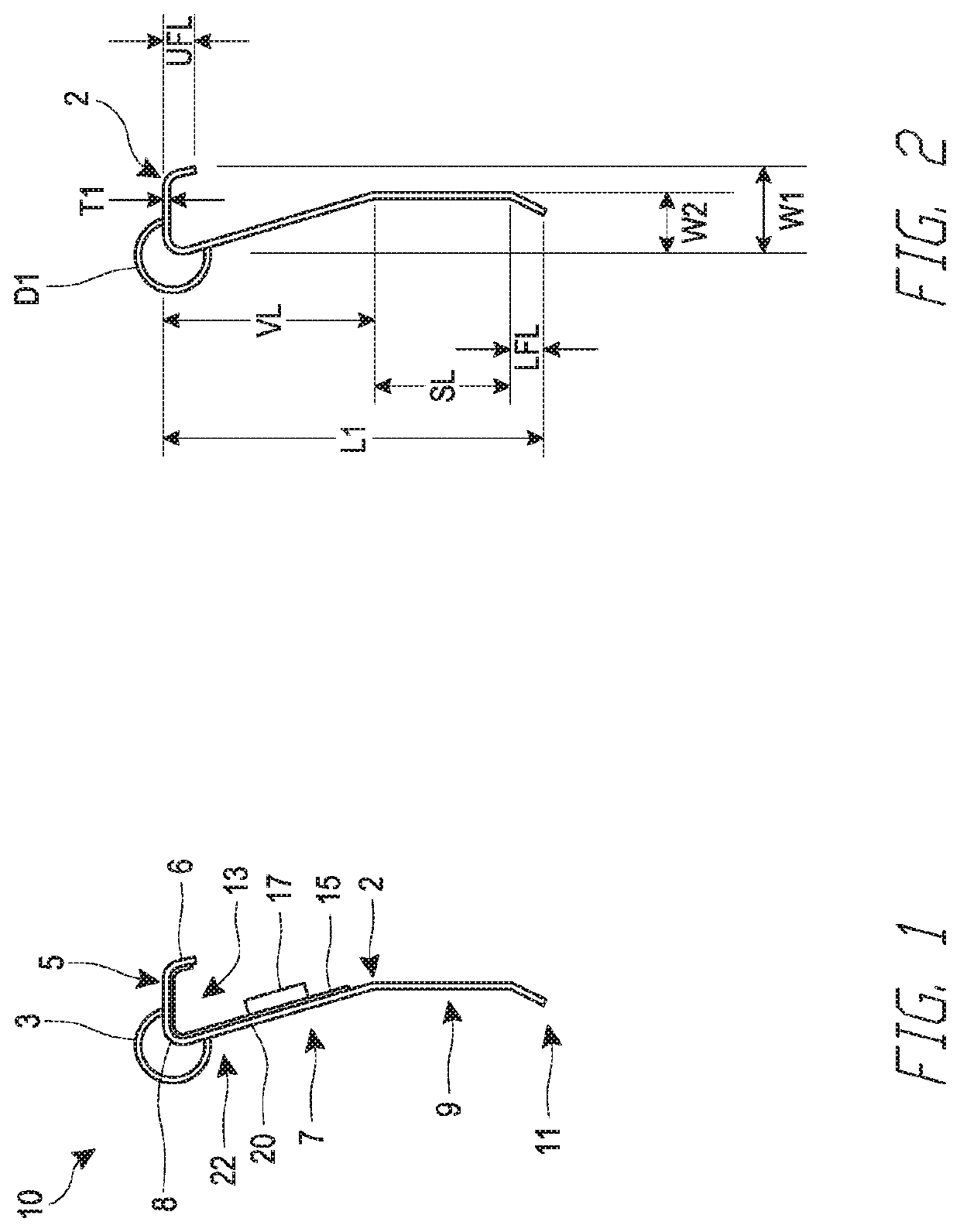
[0119]FIGS. 7-8 illustrate a fire-blocking component, in the form of a gasket profile 201. In certain implementations, the gasket profile 201 can be formed in various lengths (e.g., 5′, 10′, 12′ or other) each preferably having the same cross section throughout. The gasket profile 201 can be used in the assembly 100, similar to the fire-blocking gasket profile 10. The fire-blocking gasket profile 201 can include a profile layer 202. The profile layer 202 can include a generally horizontal portion 205 and a leg portion 207. The profile layer 202 can include a fastening location 209. The fastening location 209 can be coupled with a lower flange 211. Similar to the component 10, the fastening location 209 of the component 201 can be referred to as or can form a planar lower portion. An upper angled portion 220 and the generally horizontal portion 205 form a non-planar upper portion 222, which partially or fully defines an air gap 213. The upper angled portion 220 can be a first portion...

third embodiment

[0122]FIG. 9-10 illustrate a fire-blocking component, in the form of a gasket profile 301. The gasket profile 301 can be used in the assembly 100, similar to the fire-blocking gasket profile 10. In certain implementations, the gasket profile 301 can be formed in various lengths (e.g., 5′, 10′, 12′ or other) each preferably having the same cross-sectional shape throughout. The fire-blocking gasket profile 301 can include a profile layer 302. The profile layer 302 can include a generally horizontal portion 305. The horizontal portion 305 can be connected to an upper flange 306. A leg portion 307 of the profile layer 302 can extend downwardly from the horizontal portion 305 and can include a fastening location 309. The fastening location 309 can connect to a lower flange 311. An air gap 313 can be defined between at least portions of the horizontal 305 and the leg portion 307 of the profile layer 302. In the illustrated arrangement, at least an upper angled portion of the leg portion 3...


PUM


Abstract

A fire-rated component for a fire-rated joint, such as a head-of-wall assembly, includes an elongate body having at least a first layer, which can be in the form of a polymer profile. A second layer can be or include a foil lining and a third layer can be or include an intumescent material. The elongate body, such as the first layer, defines an air gap. The foil lining and / or the intumescent material can be positioned within the air gap. A planar lower portion of the first layer of the elongate body is positioned between a header track and a wallboard in the fire-rated joint. A non-planar upper portion of the first layer of the elongate body is positioned at least partially within a deflection gap of the wall assembly and sealingly engages the ceiling.

Description

INCORPORATION BY REFERENCE[0001]Any and all applications for which a foreign or domestic priority claim is identified in the Application Data Sheet as filed with the present application are hereby incorporated by reference in their entirety.BACKGROUNDField[0002]The disclosure generally relates to fire-rated building structures. In particular, the disclosure relates to fire-rated joint systems, wall assemblies, and other building structures that incorporate the fire-rated joint systems.Description of Related Art[0003]Fire-rated construction components and assemblies are commonly used in the construction industry. These components and assemblies are aimed at inhibiting or preventing fire, heat, or smoke from leaving one room or other portion of a building and entering another room or portion of a building. The fire, heat or smoke usually moves between rooms through vents, joints in walls, or other openings. The fire-rated components often incorporate fire-retardant materials which sub...

Claims


Application Information

Patent Timeline
Patent Type & Authority Applications(United States)
IPC IPC(8): E04B1/94
CPCE04B1/948E04B1/947E04B2/7457
Inventor PILZ, DONALD ANTHONYELLICOTT, TYLER
Owner CEMCO LLC
Learn More