Computer-assisted ascertainment of a movement of an apparatus

a technology of ascertaining and moving an apparatus, applied in the direction of programme control, electric programme control, programme-controlled manipulators, etc., to achieve the effect of high speed and efficient linkage to on

Active Publication Date: 2019-11-21
SIEMENS AG
View PDF0 Cites 2 Cited by
  • Summary
  • Abstract
  • Description
  • Claims
  • Application Information

AI Technical Summary

Benefits of technology

[0012]It may be expedient to subdivide the movement of the tool into partial movements. By way of example, it may be expedient to set the first partial movement, in which the tool is intended to be moved in free space without carrying out a process, in the first configuration space if the first partial movement in free space can be formulated more efficiently in the first configuration space than in the second configuration space. Conversely, it may be the case that the second partial movement, in which the tool should carry out a process, can be formulated more efficiently in the second configuration space than in the first configuration space. By way of example, it may be the case that the first partial movement in the first configuration space is described by a first section of the first movement trajectory with a straight embodiment while the second partial movement is described by a curved section of the first movement trajectory in the first configuration space. Conversely, it may be the case that the second partial movement in the second configuration space is described by a second section of the second movement trajectory with a straight embodiment while the first partial movement in the second configuration space is described by a curved section of the second movement trajectory. What lends itself in this case is setting the movement of the tool in such a way that the partial movements are set by sections of the movement trajectories each with a straight embodiment in the respective configuration spaces.
[0013]An advantage over existing methods for ascertaining a movement of an apparatus consists of the apparatus not needing to be stopped at a transition from the first partial movement to the second partial movement of the tool if the movement is planned on the basis of the present computer-assisted method. This is due to the fact that the movement is planned in both configuration spaces with the predetermined boundary conditions being observed. Previous approaches had the disadvantage that the partial movements set in the different configuration spaces were only planned in the corresponding configuration space in each case. By contrast, the entire movement is planned in both configuration spaces in the present method, as a result of which there can be a fluid transition from the first to the second partial movement, i.e., without stopping and at a relatively high speed. Advantageously, this allows the partial movements of the tool to be efficiently linked to one another.

Problems solved by technology

Previous approaches had the disadvantage that the partial movements set in the different configuration spaces were only planned in the corresponding configuration space in each case.

Method used


Image

  • Computer-assisted ascertainment of a movement of an apparatus
  • Computer-assisted ascertainment of a movement of an apparatus
  • Computer-assisted ascertainment of a movement of an apparatus

Examples


Embodiment Construction

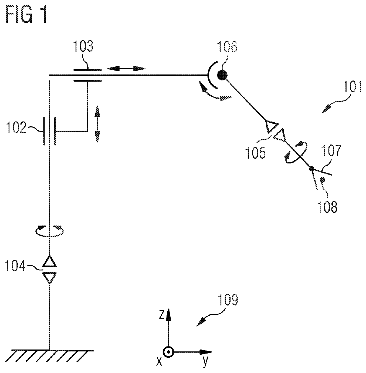
[0045]FIG. 1 schematically shows a kinematic design of an exemplary apparatus 101 comprising a tool 107 that is movable by way of translational movement axes 102, 103 and rotational movement axes 104, 105, 106 of the apparatus 101. For reasons of simplicity, movement means such as motors and drives of the apparatus 101 are not shown in FIG. 1. The apparatus 101 can be embodied as a robot, as an articulated robot or as any other type of apparatus 101 that can move the tool 107 by way of translational and / or rotational movement axes 102, 103, 104, 105, 106. The translational movement axes 102, 103 are embodied as linear articulations. The rotational movement axes 104, 105, 106 can be embodied in the form of articulations or hinges. Rigid connecting elements are formed between two articulations of the apparatus 101. Movement options of the connecting elements are indicated by double-headed arrows in FIG. 1.

[0046]The apparatus 101 has a first translational axis 102 and a second translat...


PUM


Abstract

Provided is a computer-assisted method for ascertaining a movement of an apparatus, which has a tool that is movable by way of translational and/or rotational axes of movement of the apparatus, includes the following method steps: a first movement trajectory of the tool is ascertained in a first configuration space. A predetermined parameter of a movement of the tool is optimized when ascertaining the first movement trajectory. A check is carried out as to whether the first movement trajectory satisfies at least one predetermined first boundary condition. A second movement trajectory of the tool in a second configuration space is ascertained by transforming the first movement trajectory into the second configuration space if the first movement trajectory satisfies the predetermined first boundary condition. A check is carried out as to whether the second movement trajectory satisfies at least one predetermined second boundary condition.

Description

CROSS-REFERENCE TO RELATED APPLICATIONS[0001]This application claims priority to EP Application No. 18172937.7, having a filing date of May 17, 2018, the entire contents of which are hereby incorporated by reference.FIELD OF TECHNOLOGY[0002]The following relates to a computer-assisted method for ascertaining a movement of an apparatus, and a computer program product and a system for carrying out the method.BACKGROUND[0003]The prior art has disclosed methods for planning the movement of apparatuses. One option for planning a movement of an apparatus is the so-called teach-in method, in which an apparatus is driven into predetermined positions by means of a controller. The positions are stored and driven to again within the scope of carrying out a movement (point-to-point control).[0004]The patent document DE 10 2008 057 142 B4 has disclosed a method for computer-assisted movement planning for a robot. Spatial positions of a spatial point assigned to the robot in a fixed coordinate sy...

Claims


Application Information

Patent Timeline
Patent Type & Authority Applications(United States)
IPC IPC(8): B25J9/16
CPCB25J9/1666B25J9/1676B25J9/1612G05B19/19G05B2219/35349B25J9/1664
Inventor NEUBAUER, WERNERSCHMITT, PHILIPP SEBASTIAN
Owner SIEMENS AG
Why Eureka
Try Eureka