
Projection display device, method of controlling projection display device, and program for controlling projection display device

Active Publication Date: 2019-11-07
FUJIFILM CORP
View PDF0 Cites 0 Cited by
  • Summary
  • Abstract
  • Description
  • Claims
  • Application Information

AI Technical Summary

Benefits of technology

The invention is a projection display device, method, and computer-readable recording medium that can prevent image quality degradation caused by changes in the distribution of light from the device's semiconductor light source.

Problems solved by technology

Consequently, the intensity distribution of the light that is incident upon the illumination surface of the light modulation element may not be in accordance with the design due to the aforementioned variations.
When a deviation occurs in this intensity distribution, this causes a reduction in image quality, such as brightness unevenness and color unevenness, of an image that is displayed.
Therefore, the intensity distribution of light that is incident upon the light modulation element cannot be measured.
Consequently, a reduction in the image quality of the displayed image caused by the variations in the intensity distribution cannot be prevented.

Method used


Image

  • Projection display device, method of controlling projection display device, and program for controlling projection display device
  • Projection display device, method of controlling projection display device, and program for controlling projection display device
  • Projection display device, method of controlling projection display device, and program for controlling projection display device

Examples


Embodiment Construction

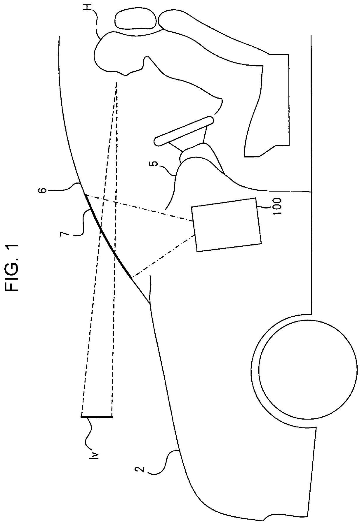
[0028]FIG. 1 is a schematic view illustrating a general configuration of an automobile 2 in which a HUD 100, which is an embodiment of a projection display device of the present invention, is mounted. The HUD 100 can be mounted and used in a vehicle other than an automobile, such as a train, a heavy machine, a construction machine, an aircraft, a ship, or an agricultural machine.

[0029]The HUD 100 is built in a dashboard 5 of the automobile 2, and projects image light on a projection surface 7 that is provided at a windshield 6 of the automobile 2 and that is processed to reflect light. By reflected light of the image light, a virtual image Iv based on the image light is displayed beyond and forwardly of the windshield 6.

[0030]By viewing the virtual image Iv displayed forwardly of the windshield 6, a driver H can recognize information, such as a picture or a character or the like, for supporting operations of the automobile 2.

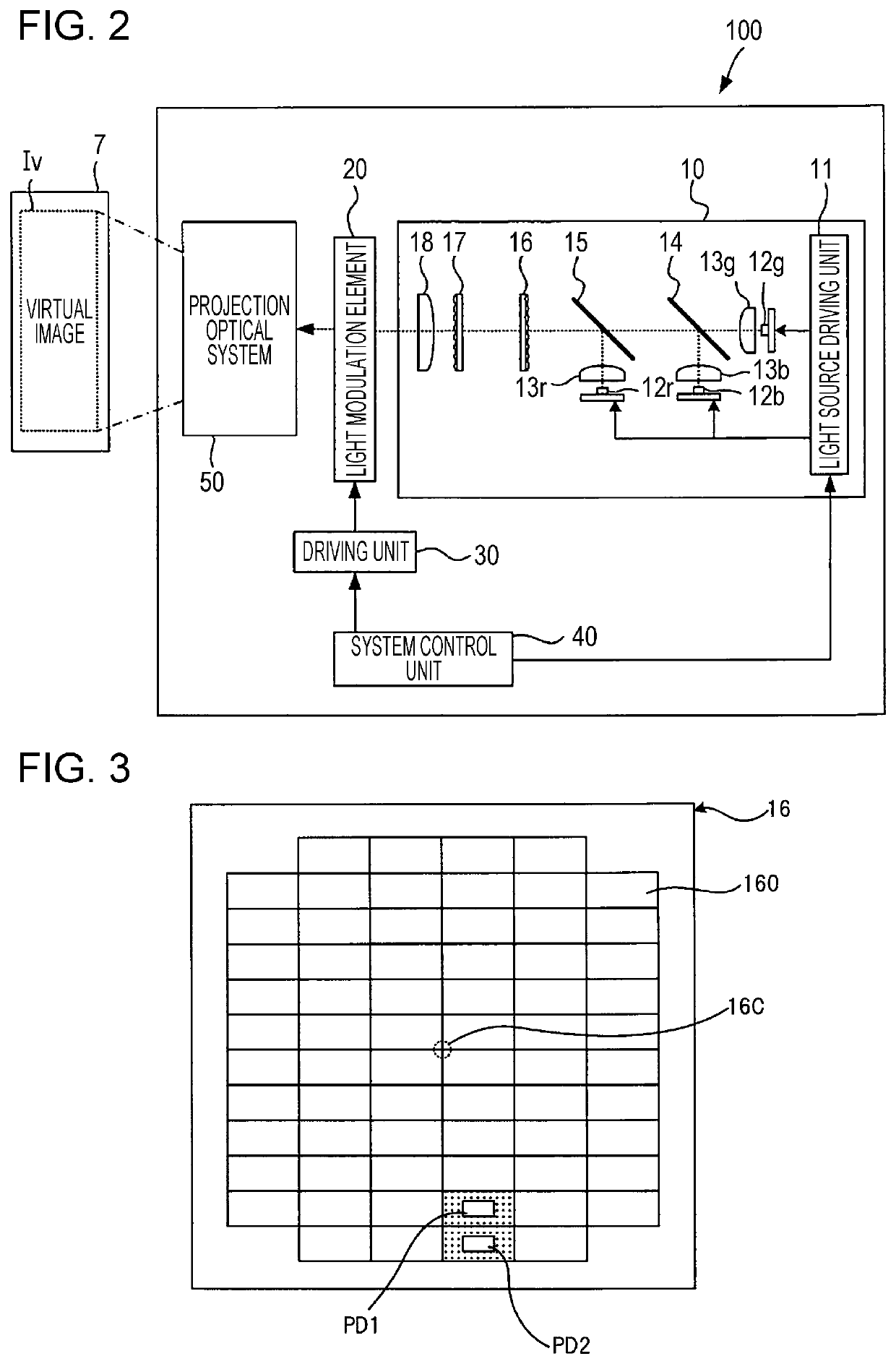
[0031]FIG. 2 is a schematic view illustrating an internal ...


PUM


Abstract

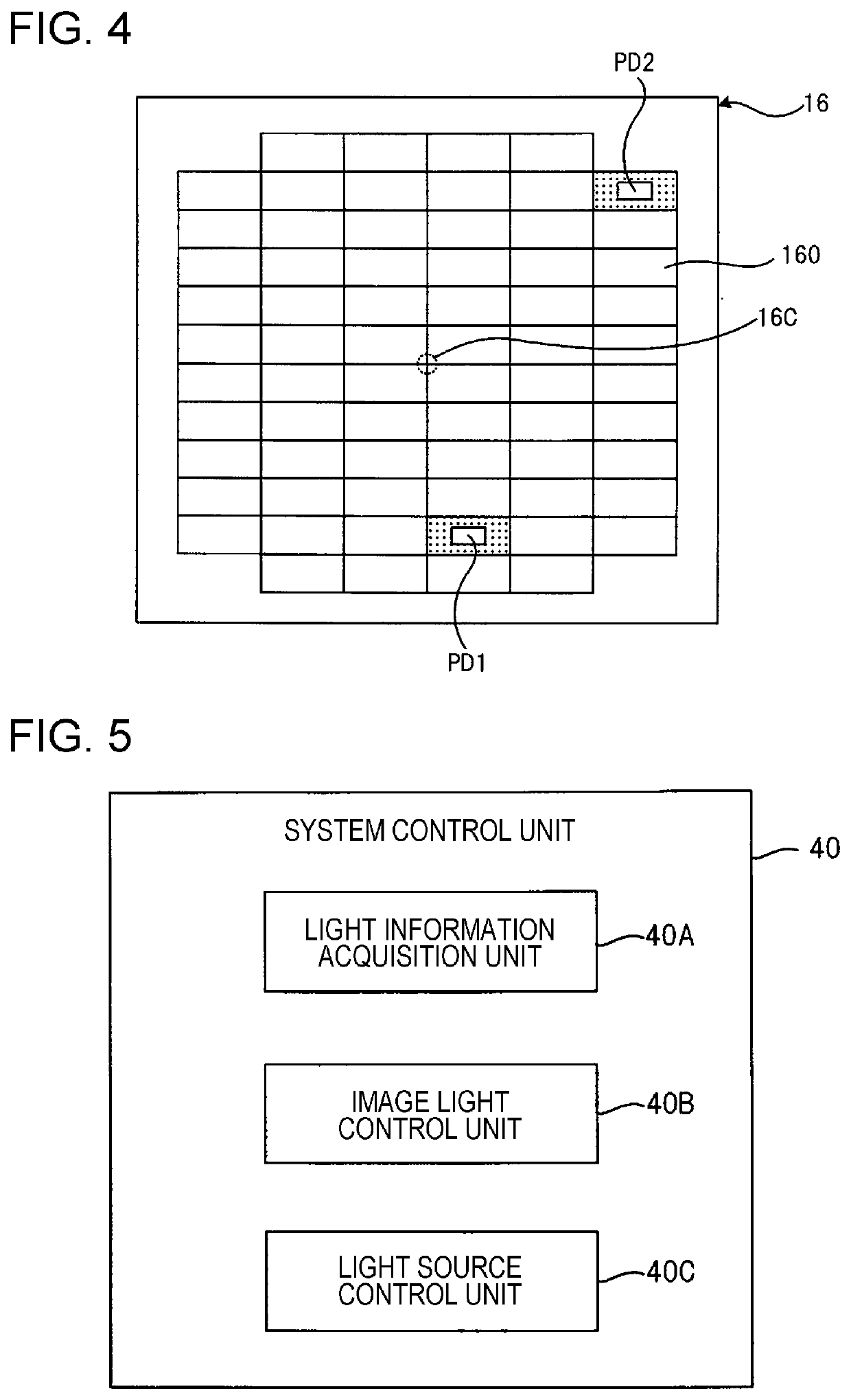
A HUD 100 includes a R light source 12r, a G light source 12g, and a B light source 12b; collimating lenses 13r, 13g, and 13b that are arranged forwardly of the light sources; fly-eye lenses 16 and 17 that are arranged side by side on an optical path of light that exits from the collimating lenses; a light modulation element 20 that, based on image information, performs spatial modulation on light that has passed through the fly-eye lenses; a projection optical system 50 that projects image light onto a projection surface 7, the image light acquired by the spatial modulation by the light modulation element; photodetection elements PD1 and PD2 that are fixed to a portion of the fly-eye lens 16; and an image light control unit 40B that controls a brightness distribution of the image light based on a brightness of light detected by each of the photodetection elements.

Description

CROSS-REFERENCE TO RELATED APPLICATIONS[0001]This application is a Continuation of PCT International Application No. PCT / JP2018 / 000316 filed on Jan. 10, 2018, which claims priority under 35 U.S.C. § 119(a) to Japanese Patent Application No. 2017-032260 filed on Feb. 23, 2017. Each of the above application(s) is hereby expressly incorporated by reference, in its entirety, into the present application.BACKGROUND OF THE INVENTION1. Field of the Invention[0002]The present invention relates to a projection display device, a method of controlling a projection display device, and a non-transitory computer readable recording medium storing a program for controlling a projection display device.2. Description of the Related Art[0003]As light sources of a projector, LEDs (light emitting diodes) or semiconductor lasers are used instead of conventional cold cathode fluorescent lamp or ultrahigh pressure mercury lamps, to increase a color reproduction range.[0004]Unlike cold cathode fluorescent l...

Claims


Application Information

Patent Timeline
IPC IPC(8): G03B21/20G03B21/16
CPCG03B21/16G03B21/2053G03B21/206H04N5/74G03B21/208G03B21/2086H04N9/3182H04N9/3194
Inventor ASUMA, NOBUKO
Owner FUJIFILM CORP
Learn More