
Standby generator control and access panel

Active Publication Date: 2019-11-07
CHAMPION POWER EQUIP
View PDF0 Cites 1 Cited by
  • Summary
  • Abstract
  • Description
  • Claims
  • Application Information

AI Technical Summary

Benefits of technology

This patent describes a control system for a standby generator that includes a control box mounted in the generator enclosure with a control panel that opens for easy access to the control components. The control panel can be closed with a fastener and all the necessary control components are mounted inside the control box. The control system also includes a cover for the control box that can be opened and closed to provide access to the control components. The cover may also have a microswitch to disengage the control components when the cover is opened. The standby generator includes a standalone enclosure with a cover that rotates between open and closed positions to provide access to the control system. The cover can cover the top portion of the control box when closed and uncover it when opened. The technical effects of this patent are improved access to the standby generator control components for easy maintenance and operation.

Problems solved by technology

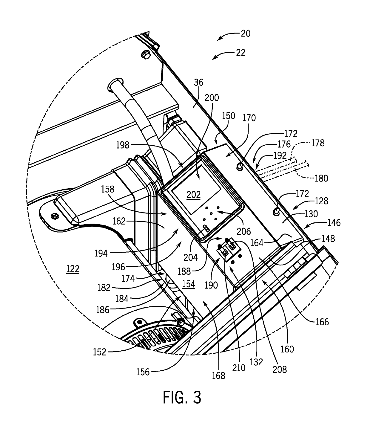
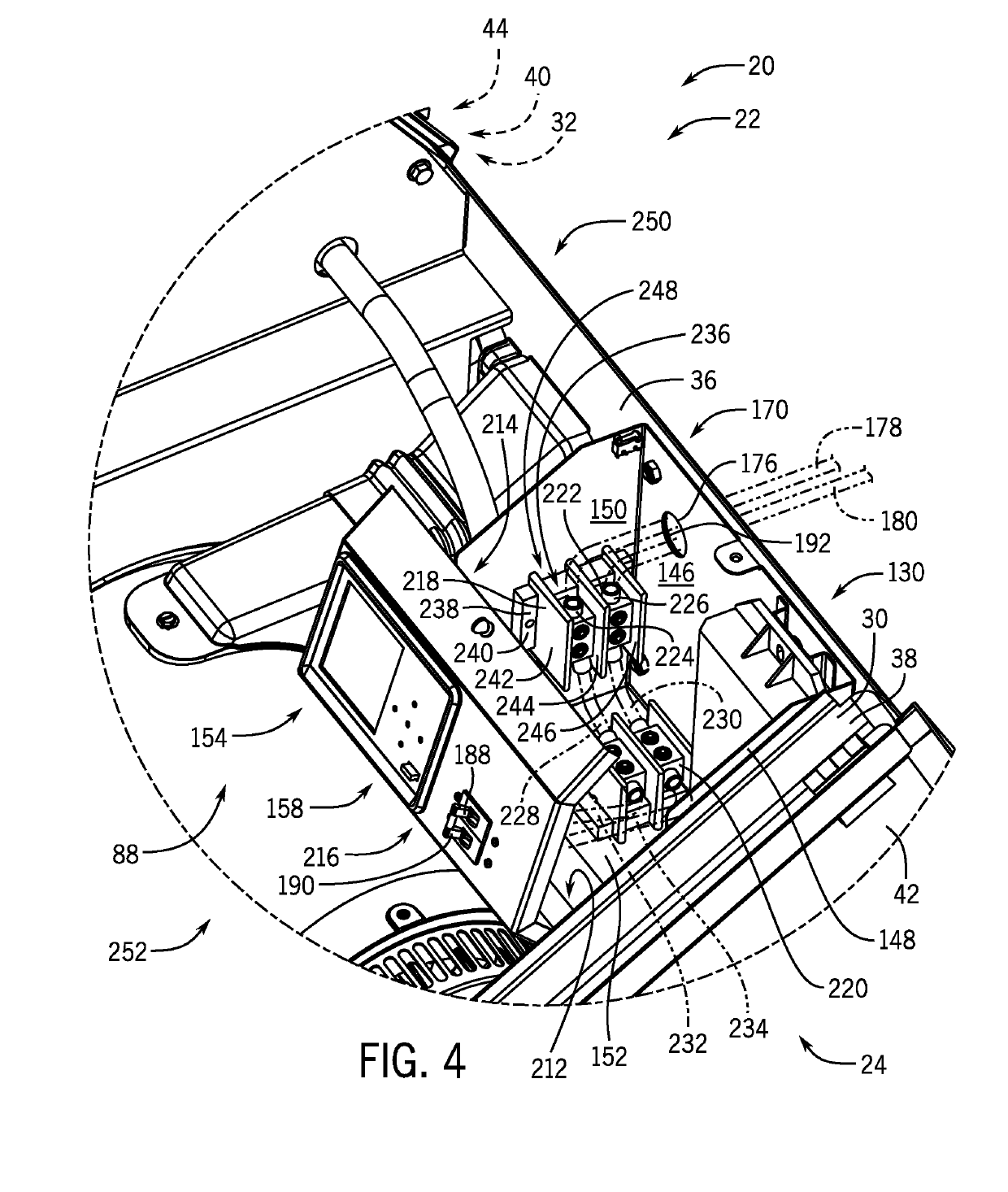
Unfortunately, installing the power distribution line in the generator can be time consuming and dangerous due to space limitations between the generator and the home or building.
The access panel may require time consuming disassembly, and limited space behind the generator may restrict access into the generator enclosure.
A person installing the distribution line may be required to reach far into the enclosure while assuming a posture that is awkward and unsafe.
Further, connection terminals for the power distribution lines may be located out of sight behind other generator components and with limited space for tools.

Method used


Image

  • Standby generator control and access panel
  • Standby generator control and access panel
  • Standby generator control and access panel

Examples


Embodiment Construction

[0023]The operating environment of the invention is described with respect to a standby generator. However, those skilled in the art will appreciate that the invention is equally applicable for use with portable or other electrical generators. While the invention will be described with respect to a standby generator having a multi-chamber generator enclosure, embodiments of the invention are equally applicable for use with single-chamber or other types of generator enclosures.

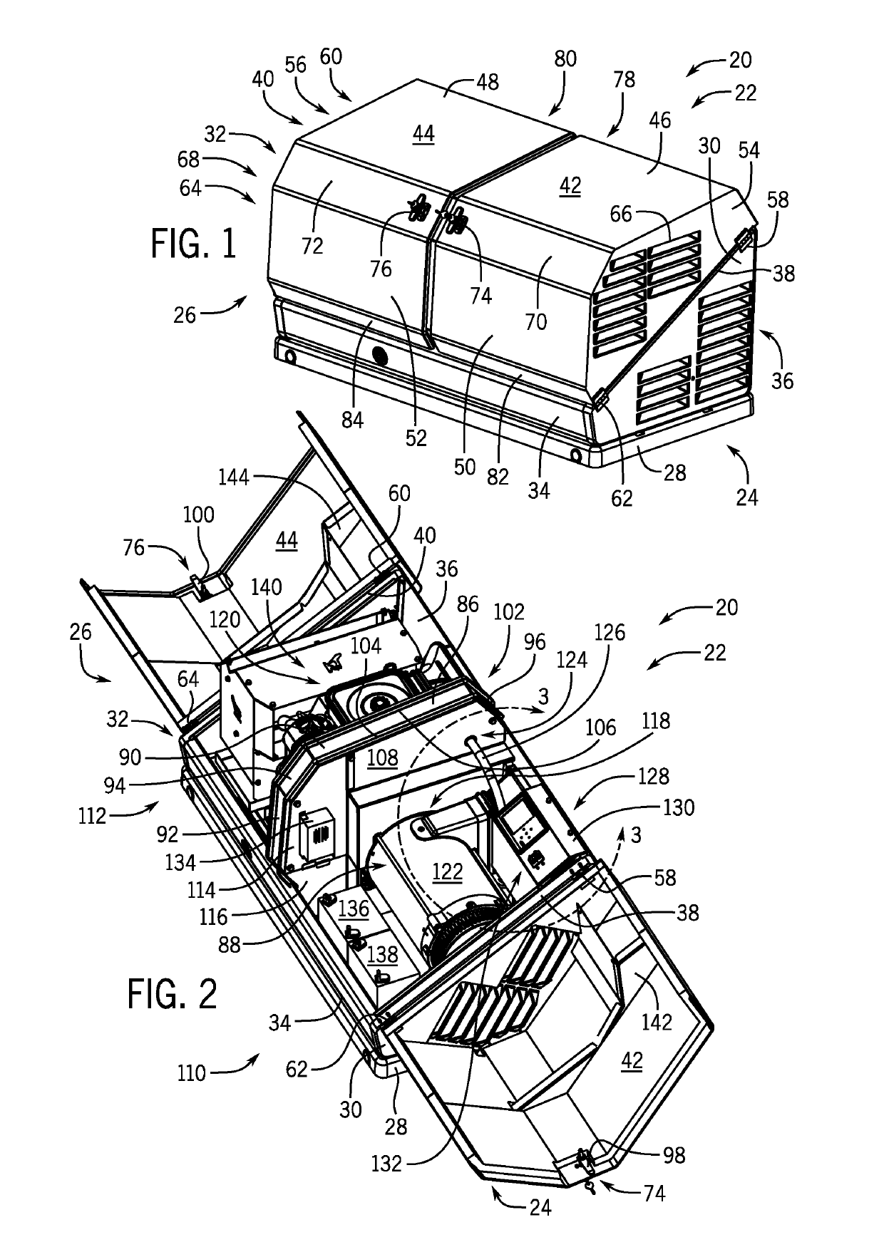
[0024]Referring to FIG. 1, a standby generator 20 is shown, in accordance with an embodiment of the invention. The standby generator 20 produces electrical energy and may deliver the electrical energy to a distribution panel of a home, office, shop, business or any other building requiring electricity. The standby generator 20 may include an internal combustion engine, an alternator driven by the internal combustion engine, and other associated components. The internal combustion engine operates on a fuel sourc...


PUM


Abstract

A control system for a standby generator includes a control box mounted in a standby generator enclosure with a control panel coupled to the control box that is selectively openable to provide access into the control box. One or more fasteners may be mounted to the control panel to selectively hold the control panel closed, and one or more generator control components may be mounted in the control box and operated by the control panel.

Description

CROSS-REFERENCE TO RELATED APPLICATION[0001]The present application is a non-provisional of, and claims priority to, U.S. Provisional Patent Application Ser. No. 62 / 667,747, filed May 7, 2018, the disclosure of which is incorporated herein by reference in its entirety.BACKGROUND OF THE INVENTION[0002]Embodiments of the invention relate generally to standby generators and, more particularly, to a control box mounted in a standby generator enclosure having improved access to electrical components within the control box.[0003]Standby generators provide a convenient source of backup power for use when outages occur in the utility grid. Standby generators typically contain a prime mover that drives an alternator or other electrical generator to produce electricity for distribution from the standby generator. The prime mover can be provided by an internal combustion engine configured to operate on a fuel source supplied from a fuel tank or a fuel line. The internal combustion engine has a...

Claims


Application Information

Patent Timeline
IPC IPC(8): F02B63/04
CPCF02B2063/045F02B63/044
Inventor SARDER, MARK J.DOPKE, RUSSELL J.SATO, HIROAKIJENISON, LEIGH A.
Owner CHAMPION POWER EQUIP
Learn More