
Inner barrel of an engine inlet with laser-machined acoustic perforations

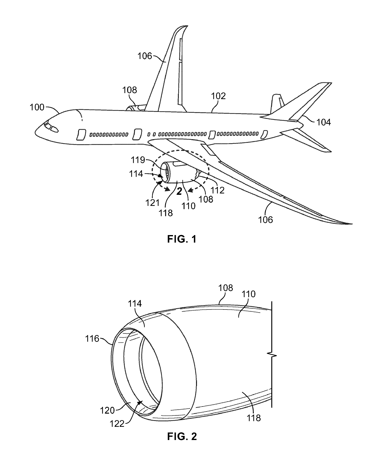
a technology of laser-machined acoustic perforation and inner barrel, which is applied in the direction of turbines, soldering devices, auxilary welding devices, etc., can solve the problems of complex and/or inefficient methods such as the inner barrel for forming perforations in acoustic structures, time-consuming, unreliable, and inability to accurately detect the noise produced by commercial airlines during takeoff and landing, etc., to achieve time-saving, energy-efficien

Active Publication Date: 2019-10-31
THE BOEING CO
View PDF3 Cites 4 Cited by
  • Summary
  • Abstract
  • Description
  • Claims
  • Application Information

AI Technical Summary

Benefits of technology

The present disclosure provides a method for accurately producing uniform perforations in an acoustic structure, such as an engine inlet assembly, in a timely, energy efficient, and cost-effective manner. The method involves attaching a face sheet to an acoustic core and controlling a femtosecond laser to laser drill a plurality of perforations in the face sheet without burning portions of the face sheet or the acoustic core surrounding the perforations. The technical effect is the improved accuracy and efficiency in the formation of perforations in an acoustic structure.

Problems solved by technology

A large portion of the noise produced by a commercial airliner during takeoff and landing is generated by gas turbine engines commonly used on airliners.
Conventional methods for forming perforations in acoustic structures, such as the inner barrel, are complex and / or inefficient.
For example, some known methods utilize routers and / or drills to mechanically drill the perforations, which can be time consuming, unreliable, and imprecise.
The conventional laser drilling methods may be relatively energy intensive and melt and / or burn the material of the inner barrel surrounding the perforations due to high thermal conduction from the laser beams.

Method used


Image

  • Inner barrel of an engine inlet with laser-machined acoustic perforations
  • Inner barrel of an engine inlet with laser-machined acoustic perforations
  • Inner barrel of an engine inlet with laser-machined acoustic perforations

Examples


Embodiment Construction

[0019]The foregoing summary, as well as the following detailed description of certain embodiments will be better understood when read in conjunction with the appended drawings. As used herein, an element or step recited in the singular and preceded by the word “a” or “an” should be understood as not necessarily excluding the plural of the elements or steps. Further, references to “one embodiment” are not intended to be interpreted as excluding the existence of additional embodiments that also incorporate the recited features. Moreover, unless explicitly stated to the contrary, embodiments “comprising” or “having” an element or a plurality of elements having a particular property may include additional elements not having that property.

[0020]Certain embodiments of the present disclosure provide systems and methods for forming noise abatement structures having perforations formed into an inner face sheet of an acoustically treated structure, such as an acoustic inlet barrel of an airc...


PUM

PropertyMeasurementUnit
frequenciesaaaaaaaaaa
diametersaaaaaaaaaa
diametersaaaaaaaaaa

Abstract

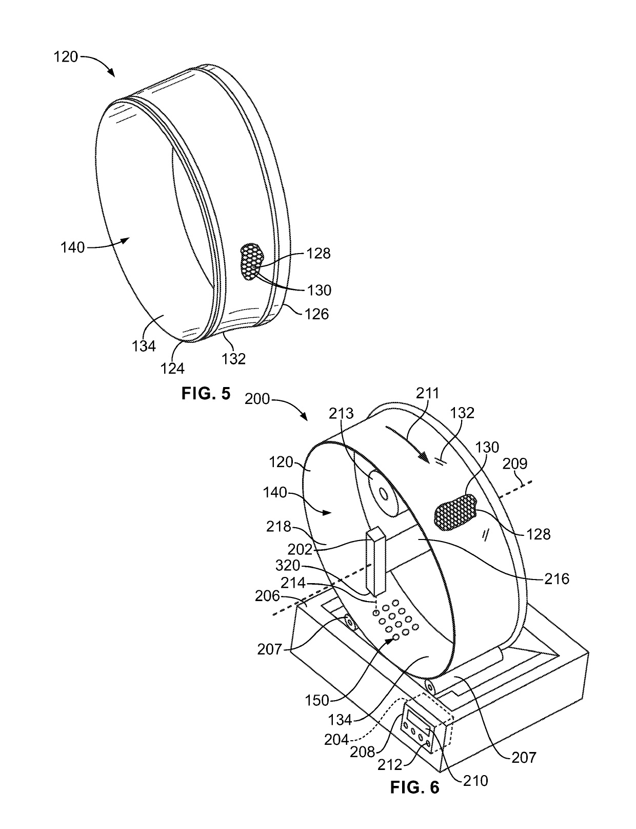
A forming system includes a femtosecond laser and a control unit that includes one or more processors operatively connected to the femtosecond laser. The femtosecond laser is configured to emit laser pulses onto an inner surface of a face sheet of an acoustic inner barrel. The acoustic inner barrel includes an acoustic core comprising an array of hexagonal cells attached to an outer surface of the face sheet that is opposite the inner surface. The control unit is configured to control the femtosecond laser to laser drill a plurality of perforations in the face sheet via emitting laser pulses at pulse durations between about 100 femtoseconds and about 10,000 femtoseconds and at frequencies over 100,000 Hz such that the perforations are formed without burning portions of the face sheet or the acoustic core surrounding the perforations.

Description

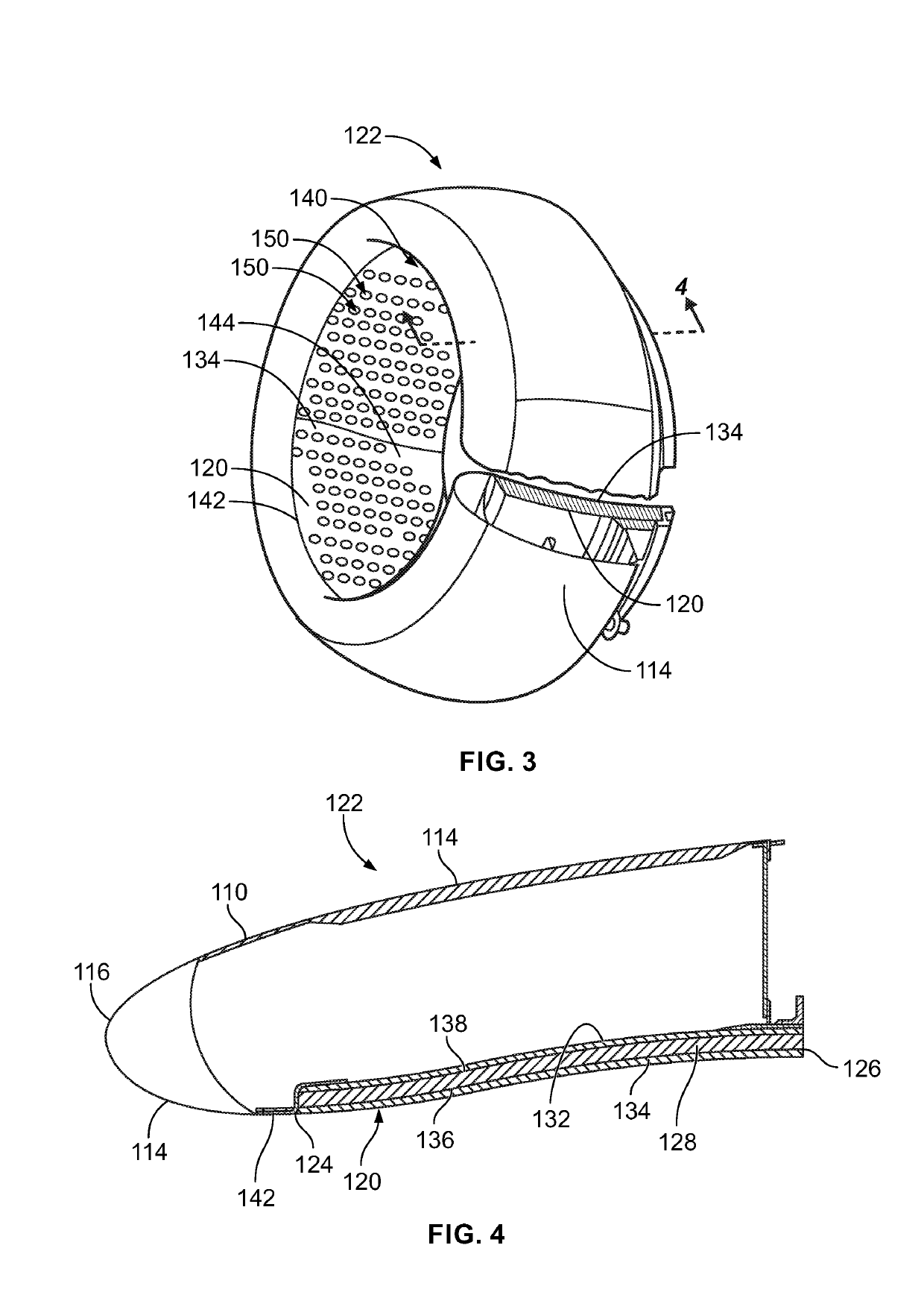
FIELD OF THE DISCLOSURE[0001]Embodiments of the present disclosure generally relate to the production of a variety of different structures that require acoustic treatment.BACKGROUND[0002]Commercial airliners are required to meet certain noise standards during takeoff and landing. A large portion of the noise produced by a commercial airliner during takeoff and landing is generated by gas turbine engines commonly used on airliners. Known methods for reducing the noise level of a gas turbine engine include acoustically treating the inlet section of the engine nacelle. In this regard, an inner barrel of a gas turbine engine inlet section may be provided with a plurality of relatively small perforations formed in the walls of the inner barrel. The perforations absorb some of the noise that is generated by fan blades rotating at high speed at the engine inlet section, and thereby reduce the overall noise output of the gas turbine engine.[0003]Conventional methods for forming perforations...

Claims


Application Information

Patent Timeline
Patent Type & Authority Applications(United States)
IPC IPC(8): B23K26/382F02C7/045
CPCB23K2101/001F05D2250/18F05D2230/13F02C7/045B23K26/389F05D2260/96F05D2220/323B23K26/382B23K26/702B23K37/0426B23K26/386B23K26/384B23K26/0624B23K26/082B23K2103/172
Inventor REEVES, JAKE ADAMNEGLEY, MARK ALANHERRERA, ERICBAUMAN, JOHN SCOTTBERTOLUCCI, BRANDON L.HORST, PERRY T.
Owner THE BOEING CO
Learn More