
Preservation system for a bowling ball

a technology for bowling balls and storage systems, applied in the field of storage systems for bowling balls, to achieve the effects of inhibiting thermal shock, high vapor pressure, and strong marketing advantages

Active Publication Date: 2019-10-17
MAGNUM SHIELDING
View PDF9 Cites 3 Cited by
  • Summary
  • Abstract
  • Description
  • Claims
  • Application Information

AI Technical Summary

Benefits of technology

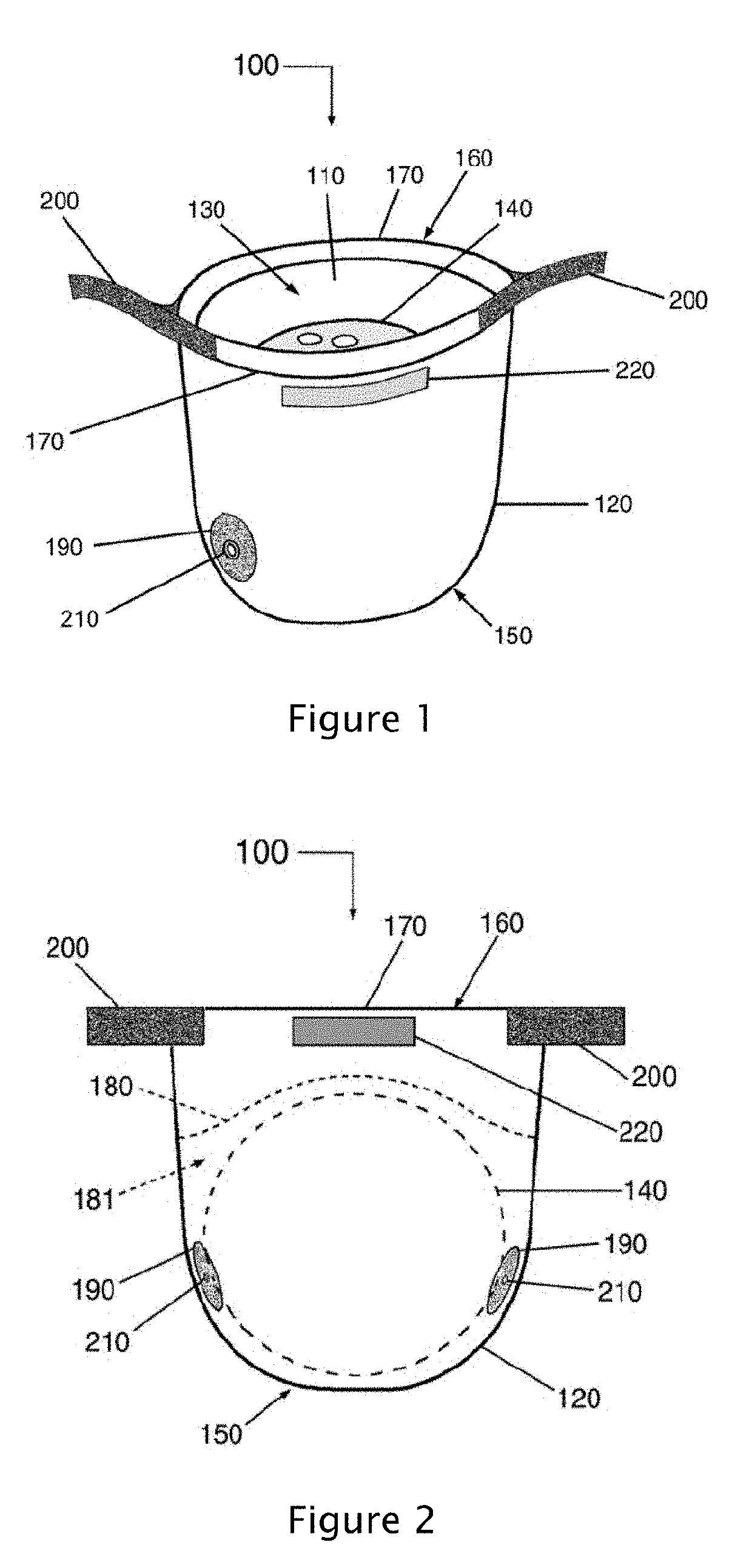
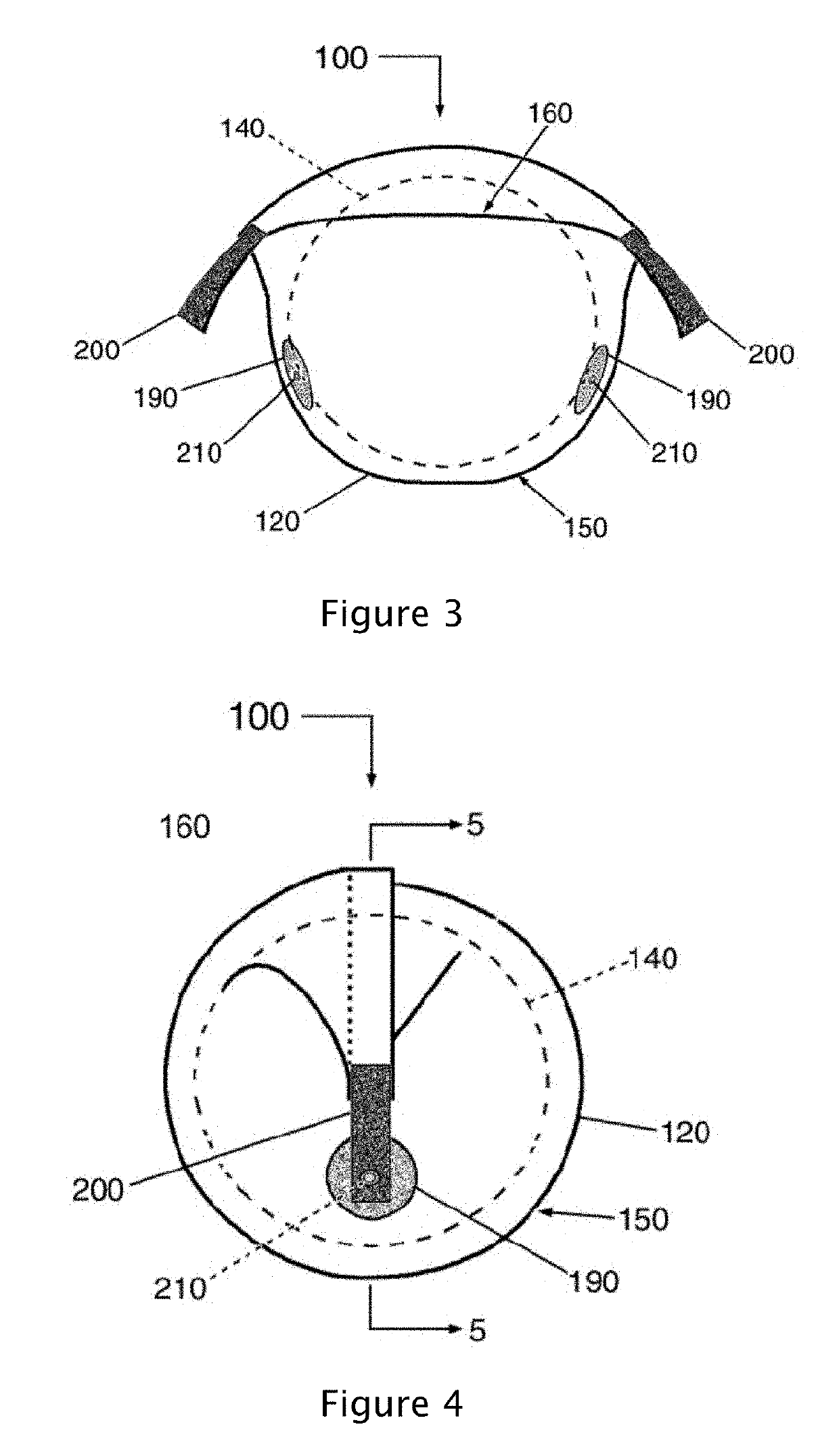
The present patent addresses the issue of a bowling ball being sensitive to changes in temperature and the evaporation of plasticizers from its outer cover. This sensitivity is caused by the additives used in current resin formulations, which create micro air pockets that enhance the evaporation process. The patent proposes a solution in the form of a bowling ball enclosure that reduces temperature fluctuations and plasticizer evaporation. The enclosure has a flexible inner vapor barrier layer and a flexible outer layer made of a polymer material, with a bottom portion and a top portion that can be opened or closed to encapsulate the bowling ball. A flexible insulation layer is used to allow the inner vapor barrier layer to contact the outer layer. The enclosure can also have a vent port for air circulation. The technical effect of this patent is to provide a solution for protecting bowling balls from environmental factors that can affect their performance.

Problems solved by technology

It has also been discovered that independent of the existence of a polar gradient within the bowling ball, as the coverstocks now formed of reactive resins, the bowling balls can have a tendency to dry or age through the evaporation of volatile molecules or plasticizers and the bleeding as well as the leaching out of plasticizers when subjected to hot seasonal temperatures, which can lead to degradation in the factory new performance characteristics of the bowling ball affecting the engagement footprint of the contact area of the surface area of the bowling ball with the bowling lane due to an increase in hardness of the bowling ball, such as an increase in the Shore D durometer, that may also result in cracking.

Method used


Image

  • Preservation system for a bowling ball
  • Preservation system for a bowling ball
  • Preservation system for a bowling ball

Examples


Embodiment Construction

[0049]The detailed description set forth below is intended as a description of various configurations of the present disclosure and is not intended to represent the only configurations in which the present disclosure may be practiced. It will be apparent, however, to those of ordinary skill in the art that the present disclosure is not limited to the specific details set forth herein and may be practiced without these specific details.

[0050]Embodiments of the present disclosure provide an apparatus and a method of providing an insulating body for encompassing at least one bowling ball. The present disclosure addresses the problems associated with temperature variations on bowling balls, which can cause resin chemicals to seep out of the bowling ball material and can cause material failures. The present disclosure also provides for retaining a relatively high concentration of resin chemicals, plasticizer, and resin vapors in the environment of the retained bowling ball so as to reduc...


PUM


Abstract

A method and a bowling ball enclosure are provided for encasing and reducing temperature fluctuations of and within a bowling ball. The bowling ball enclosure includes a flexible inner vapor barrier layer and a flexible outer layer that are made of a polymer material, the inner layer forming an interior region that receives the bowling ball. The bowling ball enclosure also includes a bottom portion and a top portion, wherein the top portion is positionable from a first position to a second position to encapsulate the bowling ball. In the first position, the top portion being in an open position to receive the bowling ball into the interior region. In the second position, the top portion being in a closed position to encapsulate the bowling bowl. A bowling ball bag includes a vapor ball layer to reducing the emission of volatiles from a retained bowling ball.

Description

BACKGROUND OF THE INVENTIONField of the Invention[0001]The present disclosure relates to an apparatus and method for encapsulating a bowling ball to reduce temperature fluctuations of a bowling ball and temperature differentials within a bowling ball so as to reduce induced coverstock cracking and core and layer separation, and to reduce accelerated resin coverstock aging through heat induced leaching of the chemicals added to resins to impart flexibility and to reduce resin coverstock aging through the evaporative aging (drying) of the bowling ball coverstock so as to reduce coverstock cracking and performance degradation.Description of Related Art[0002]A bowling ball is typically made up of multiple layers, such as a core, a filler, and a coverstock, wherein each layer of material has a different thickness and composition. Heavier bowling balls may include additional layers of greater density material or more layers of a particular material. As each layer of material has a particu...

Claims


Application Information

Patent Timeline
IPC IPC(8): A63B47/00B62B1/26
CPCB62B1/26A63B2209/00A63B2243/0054A63B47/007B62B2202/40B62B1/22A63B2209/10A63B2225/093B65D81/38
Inventor HURWITZ, SCOTT L.HURWITZ, CAMERON F.
Owner MAGNUM SHIELDING
Learn More