
Improvements in or relating to the monitoring of fluid flow

a technology of fluid flow and monitoring, applied in the direction of volume/mass flow by mechanical effect, volume/mass flow by differential pressure, testing/calibration for volume flow, etc., can solve the problem of large mis-measurement problems, inability to correct the performance of flow meters, and inability to achieve trade and most importantly safe operation. problem, to achieve the effect of facilitating the calculation of various properties

Active Publication Date: 2019-10-10
COVENTRY UNIVERSITY
View PDF0 Cites 5 Cited by
  • Summary
  • Abstract
  • Description
  • Claims
  • Application Information

AI Technical Summary

Benefits of technology

The present invention provides a method to calculate various properties of flow from a given quantity of pressure change, regardless of the physical properties of the fluid. This enables the use of differential pressure flow meters for low Reynolds number flows. The technical effect is improved accuracy and reliability in flow measurement.

Problems solved by technology

Without accurate measurement control, optimisation, trade and most importantly safe operation could not be achieved.
However, in practice this assumption is invalid and a correction factor called a discharge coefficient is used to correct practical measurements to theory.
However, these advantages only apply in high Reynolds number applications with some standards stating a lower limit of applicability of 200,000 Reynolds number (ISO 5167:2003-4 Venturis).
This effect is compounded the lower the Reynolds number is with even very small changes in Reynolds number causing large mis-measurement issues.
The issue lies in the fact that the operating Reynolds number is unknown in practice and without this it is impossible to correct the flow meters performance.
Determining the operating Reynolds number requires additional measurements of physical properties adding to cost and complexity.
Even so, it may still be difficult to determine the Reynolds number with sufficient accuracy to make reliable calculations of the flow rate.

Method used


Image

  • Improvements in or relating to the monitoring of fluid flow
  • Improvements in or relating to the monitoring of fluid flow
  • Improvements in or relating to the monitoring of fluid flow

Examples


Embodiment Construction

[0054]In order that the invention may be more clearly understood embodiments thereof will now be described, by way of example only, with reference to the accompanying drawings, of which:

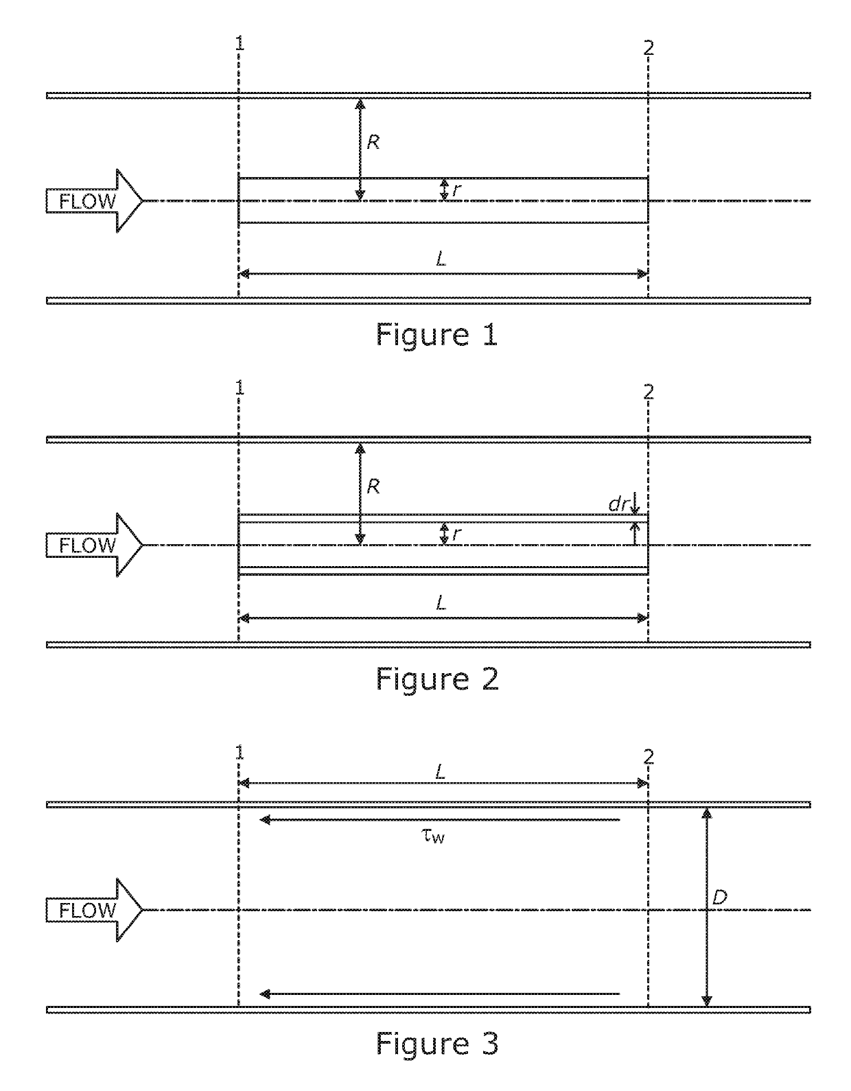
[0055]FIG. 1 illustrates fluid flow through a circular cross-section within a pipe;

[0056]FIG. 2 illustrates fluid flow through an annular element with circular cross-section within a pipe;

[0057]FIG. 3 illustrates flow through a pipe of circular cross-section;

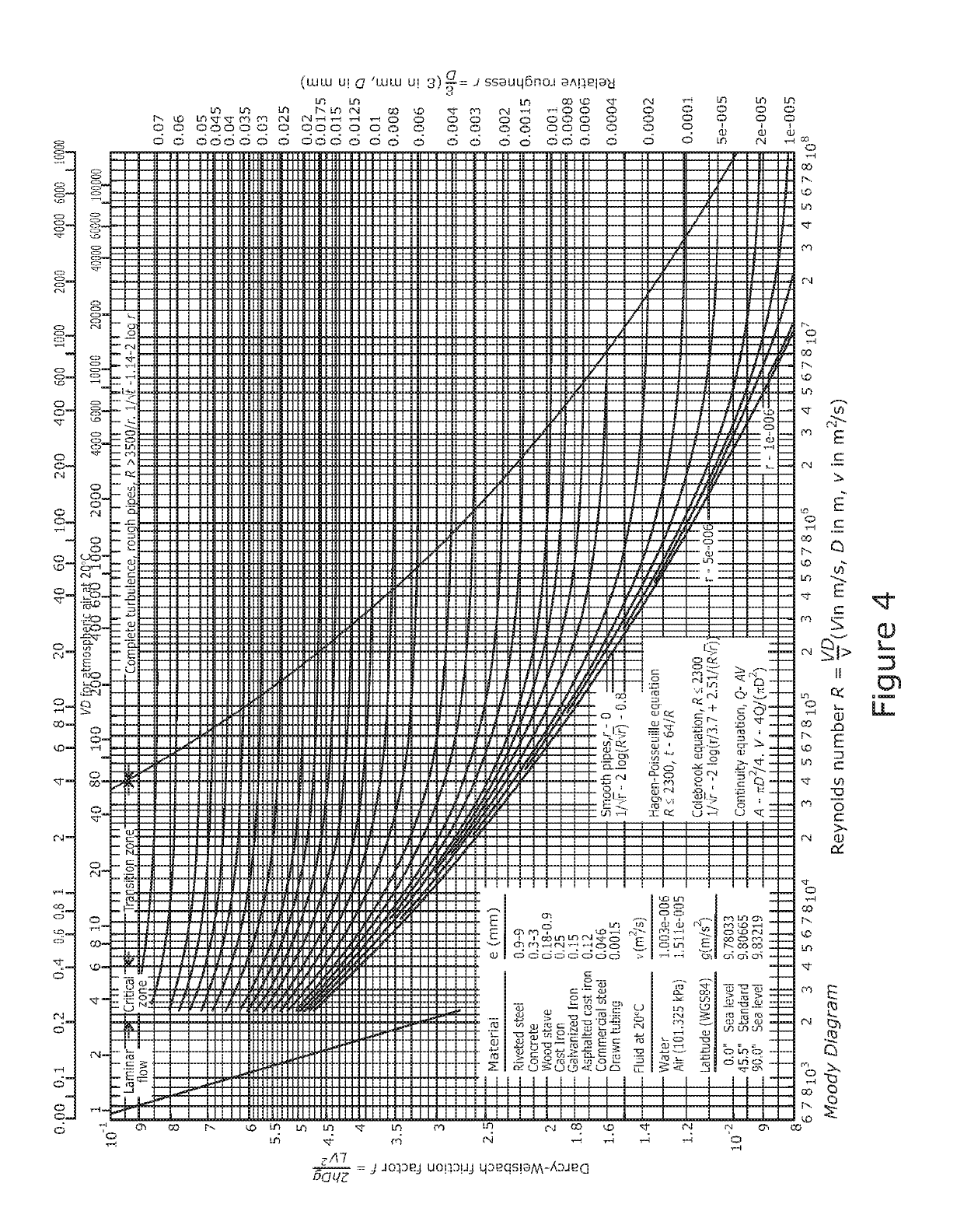
[0058]FIG. 4 is a graph illustrating the relationship between Darcy-Weisbach friction factor and Reynolds number;

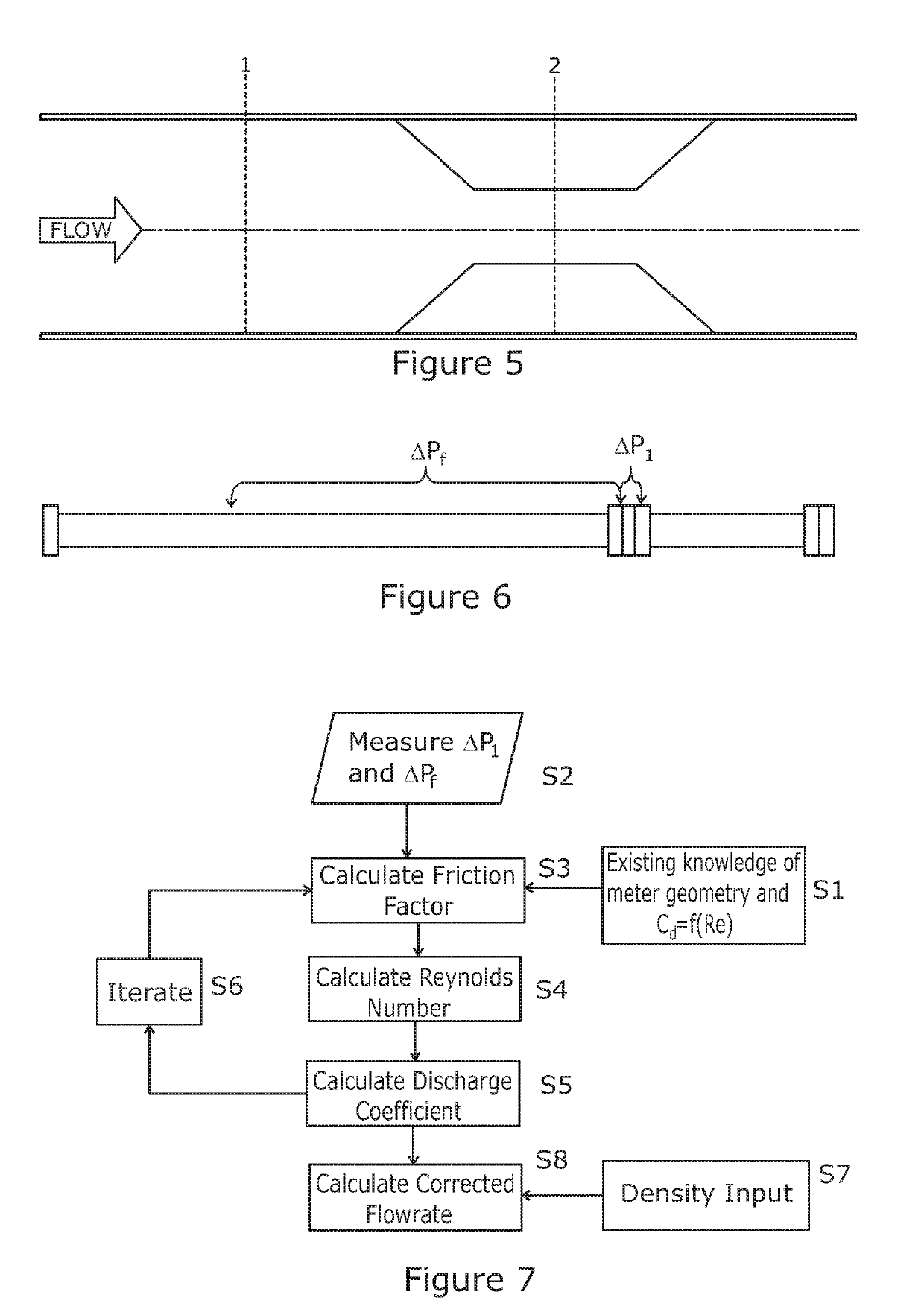
[0059]FIG. 5 illustrates fluid flow through a primary element in a circular cross-section pipe;

[0060]FIG. 6 illustrates schematically an embodiment of an apparatus for monitoring flow according to the present invention;

[0061]FIG. 7 is a flow chart illustrating an implementation of a method of flow monitoring with external density knowledge according to the present invention;

[0062]FIG. 8 is a flow chart illustrating another implementati...


PUM


Abstract

The present invention provides a method and apparatus for the measurement of a pressure differential across a differential pressure flow meter ΔP1 and the line pressure drop due to friction ΔPf along a length L of pipe. Subsequently, the quantity (formula) is calculated, enabling the inline calculation of multiple properties of the flow. Calculated flow properties include friction factor, Reynolds number, discharge coefficient, density, viscosity, and corrected flowrate. The present invention further relates to a method of calibration of a differential flow meter and a calibration apparatus for a differential flow meter utilising the same principles.

Description

TECHNICAL FIELD OF THE INVENTION[0001]The present invention relates to monitoring fluid flow. In particular, the present invention relates to monitoring of fluid flow at, but not limited to, low Reynolds numbers using differential pressure flow meters.BACKGROUND TO THE INVENTION[0002]The flow measurement of fluids is vitally important to the world economy. Not only through having accurate values for the quantities of goods bought or sold, but for the safe and continued operation of processes across all industries. Without accurate measurement control, optimisation, trade and most importantly safe operation could not be achieved. Accurate flow measurement is achieved through the use of repeatable flow meters which are applied following industry best practice.[0003]A particularly well known type of flow meter technology is called a differential pressure flow meter which is based around the use of primary element within a pipe. The primary element can have many different geometries but...

Claims


Application Information

Patent Timeline
IPC IPC(8): G01F15/02G01F1/34
CPCG01F25/0007G01F1/34G01F15/02G01F25/10
Inventor MARSHALL, CRAIG
Owner COVENTRY UNIVERSITY
Learn More