Image processing apparatus, image processing method, and image processing program
a technology of image processing and image processing method, which is applied in the direction of image enhancement, instruments, and recognition of medical/anatomical patterns, etc., can solve the problems of mammary glands, more likely to be hidden objects, and difficult to see in the case of mammary glands
- Summary
- Abstract
- Description
- Claims
- Application Information
AI Technical Summary
Benefits of technology
Problems solved by technology
Method used
Image
Examples
first embodiment
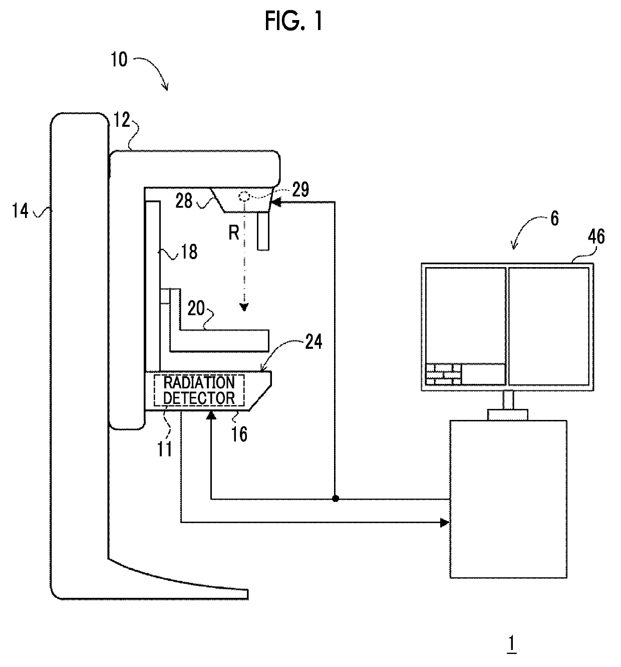
[0047]First, an example of the overall configuration of a radiography system according to this embodiment will be described. FIG. 1 is a configuration diagram illustrating an example of the overall configuration of a radiography system 1 according to this embodiment.
[0048]The radiography system 1 according to this embodiment has a function of capturing radiographic images in response to an operation of a user, such as a doctor or a radiology technician, on the basis of a command (imaging order) input from an external system (for example, a radiology information system (RIS)) through a console 6.
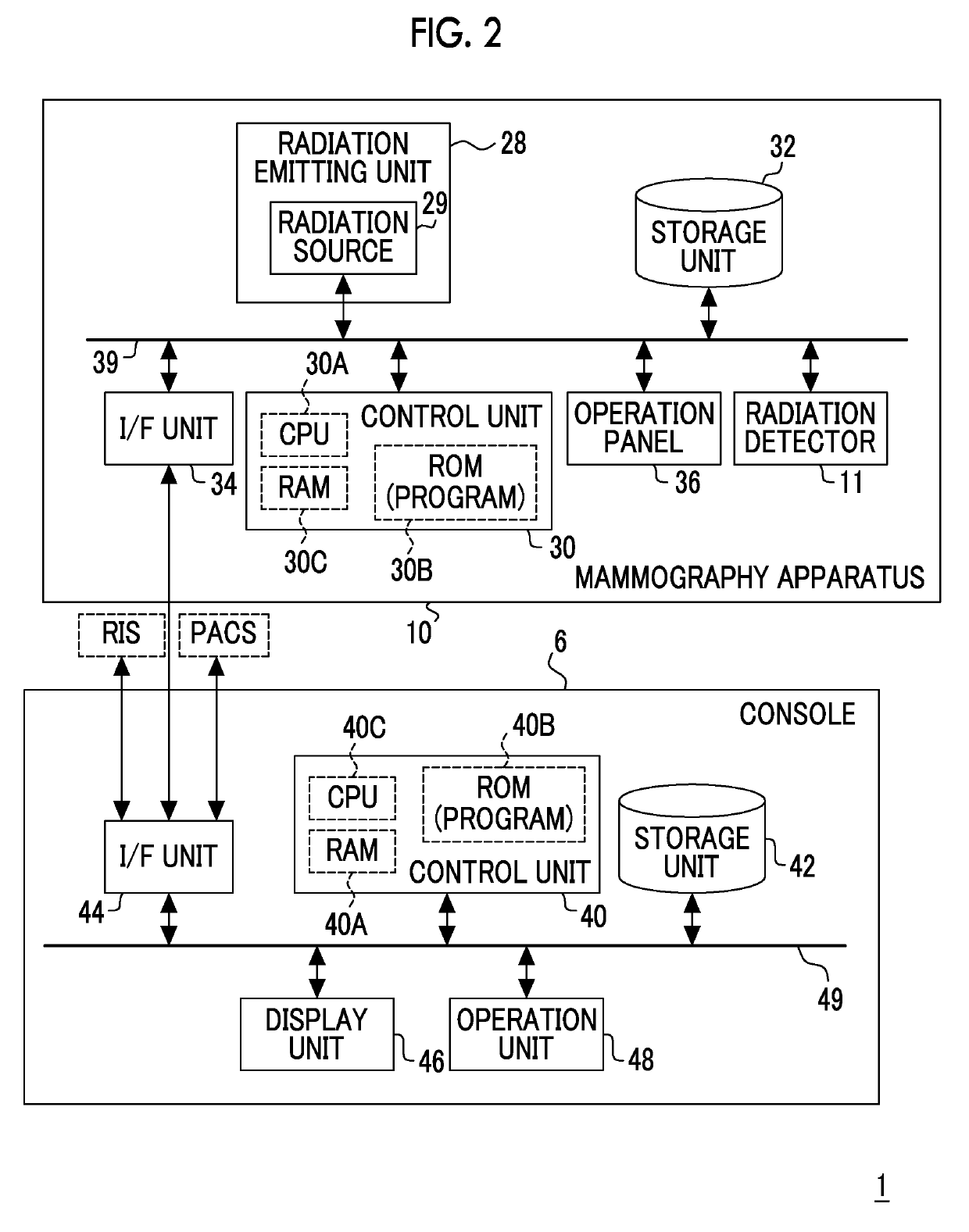
[0049]As illustrated in FIG. 1, the radiography system 1 according to this embodiment includes the console 6 and a mammography apparatus 10. FIG. 2 is a block diagram illustrating an example of the configuration of the console 6 and the mammography apparatus 10 according to this embodiment.
[0050]The console 6 according to this embodiment has a function of controlling the mammography apparatus...
second embodiment
[0105]Next, a second embodiment will be described in detail. In this embodiment, the same configurations and operations as those in the first embodiment are denoted by the same reference numerals and the detailed description thereof will not be repeated.
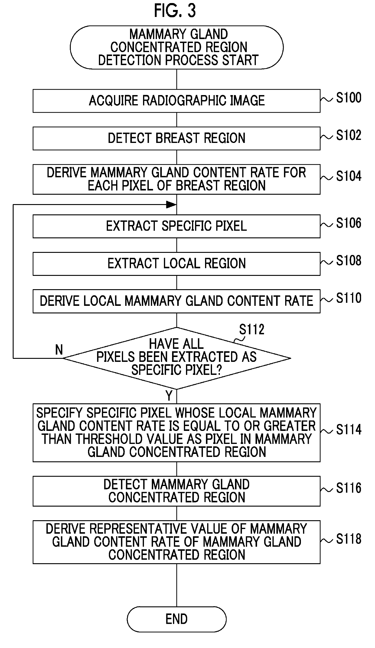
[0106]Since the configurations of a radiography system 1, a console 6, and a mammography apparatus 10 are the same as those in the first embodiment, the description thereof will not be repeated. In this embodiment, since a mammary gland concentrated region detection process performed by the control unit 40 of the console 6 is partially different from the mammary gland concentrated region detection process (see FIG. 3) in the first embodiment, different processes will be described.
[0107]FIG. 11 is a flowchart illustrating an example of the flow of the mammary gland concentrated region detection process in the console 6 according to this embodiment. In a case in which the mammary gland concentrated region detection process illustrated ...
third embodiment
[0115]Next, a third embodiment will be described in detail. In this embodiment, the same configurations and operations as those in the first embodiment are denoted by the same reference numerals and the detailed description thereof will not be repeated.
[0116]Since the configurations of a radiography system 1 and a console 6 are the same as those in the first embodiment, the description thereof will not be repeated. In this embodiment, the configuration of a mammography apparatus 10 is partially different from that in the first embodiment. The mammography apparatus 10 according to this embodiment has a so-called tomosynthesis imaging function which irradiates the breast with the radiation R emitted from the radiation source 29 at each of a plurality of irradiation angles to capture a plurality of projection images.
[0117]FIG. 12 is a block diagram illustrating an example of the configuration of the console 6 and the mammography apparatus 10 according to this embodiment. As illustrated...
PUM
 Abstract
Description
Claims
Application Information
 - R&D
- Intellectual Property
- Life Sciences
- Materials
- Tech Scout
- Unparalleled Data Quality
- Higher Quality Content
- 60% Fewer Hallucinations
Browse by: Latest US Patents, China's latest patents, Technical Efficacy Thesaurus, Application Domain, Technology Topic, Popular Technical Reports.
© 2025 PatSnap. All rights reserved.Legal|Privacy policy|Modern Slavery Act Transparency Statement|Sitemap|About US| Contact US: help@patsnap.com


